BSI has published a technical report on free form lenses: PD ISO/TR 18476: 2017 Ophthalmic optics and instruments – Free form technology –Spectacle lenses and measurement. This 30-page document is divided into five main sections: a short technical introduction, manufacture, the potential benefits of free form lens calculation and measurement and quality control.
Although single-vision free form lenses are used in, for example, sports spectacles that have significant as-worn face form (wrap) and pantoscopic angles, the text relates to progressive-power lenses since these are the most common free form ones.
Annex A shows a flow diagram of spectacle lens dispensing; this compares the process for standard lenses, free form lenses that have been specifically designed to take account of just the spectacle frame parameters, and free form personalised lenses. Annex B goes into greater detail on the measurement and quality control while Annex C is a glossary of terms.
Free form is spelt as two separate words, even though conventional usage in engineering spells it as freeform, while in the arts area, most dictionaries hyphenate the two words. This decision was made because, many years ago, one spectacle lens manufacturer had a registered trademark using the single word spelling.
The report is entirely informative – ISO rules do not allow normative data, so although there is the section ‘terms and definitions’, there are no entries, eg a formal definition of what is free form, although a description of the term is given in the glossary.
Section 4.2 discusses free form surfacing in comparison to conventional lens surfacing, explaining that free form surfacing allows the production of complex surfaces such as progressive- power surfaces directly onto the lens blank. Years ago, such processing was used to make the moulds from which semi-
finished progressive-power lenses were made. The FMO Standards panel (personal communication) suggested that a free form surface was a ‘lens surface that cannot be described by an equation, and therefore can only be produced by a numerically controlled system with three or more axes of movement’.
An exception to this would be an atoroidal surface, which can probably be defined mathematically but cannot be produced by conventional surfacing. Importantly, this Technical Report states that a lens made on free form equipment that could have been made on conventional machinery should not be described as a free form lens.
To avoid excessive detail and different names given by the many manufacturers to their products, the report uses customisation to include lenses corrected solely for the prescription, particularly astigmatic corrections at oblique axes, and those additionally corrected for the as-worn position and wearer needs.
Section 4.3 points out that the free form process does not necessarily lead to a visual benefit for the wearer. The result will depend upon the software generating the surface description for the free form generator.
For example, although not in the report, the software could simply ‘add’ the curvatures needed for the distance prescription parameters to that for a traditional front surface progressive, thus enabling a back surface progressive power lens with a spherical front surface. While this may be more convenient for the manufacturer, there is no element of bespoke design.
Section 5 on manufacturing compares a conventional (perhaps ‘traditional’ would have been a better word) approach to that used with free form generation. Table 1 gives a very good over-view of the differences between the two methods, and some of the advantages of the free form method. Table 2 points out that the responsibility for maintaining good quality free form lenses now falls entirely on the laboratory, whereas conventional methods relied on the quality of the semi-finished lens for the complicated surface.
Section 6 on the potential benefits of free form lens calculation details the effects of oblique astigmatism (from the oblique ray path through lenses, not just oblique astigmatism in refractive errors), best form lenses and the compromises when using semi-finished lens blanks resulting from a limited range of distance portion curves with each curve covering a range of prescriptions instead of the optimum curve for the prescription.
An illustration of the improvement in lens characteristics with optimisation for prescription and then both prescription and as-worn position (position of wear) is well worth studying and remembering when dispensing – see figure 1.
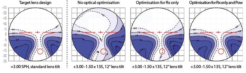
Figure 1: Comparison of the size and position of the clear zones of a progressive-power lens with oblique astigmatism. The diagrams show the target design, a lens with no optimisation, and the improvements with optimisation for the prescription and even better, also with position of wear. Values determined by ray tracing. Power values given in dioptres. Linear dimensions given in millimetres. (Image by Darryl Meister. Reproduced with permission from Carl Zeiss Vision International GmbH)
The need for measuring the as-worn face form and pantoscopic angles is discussed in 6.5, together with the need to verify lenses against the manufacturer’s verification power which is the power expected to be found when checking the lenses on a focimeter. The benefits of small increments in corridor height are illustrated in figure 2, though the reviewer would prefer a larger area of the near portion to be included within the frame’s aperture.
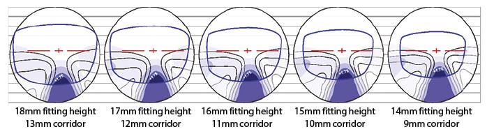
Figure 2: Customisation of the corridor length in small increments for the frame size and, hence, fitting height (Image by Darryl Meister. Reproduced with permission from Carl Zeiss Vision International GmbH)
Figure 3 shows the results of biasing the lens design towards near vision, distance vision, or the more usual balanced design.
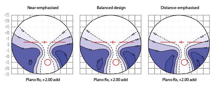
Figure 3: Personalisation of the lens design depending upon the visual requirements. Power values given in dioptres. Linear dimensions given in millimetres. (Image by Darryl Meister. Reproduced with permission from Carl Zeiss Vision International GmbH)
Section 7 on measurement and quality control briefly mentions verification in practice or laboratory where just the distance power, near power or addition power and prism need to be verified to comply with standards. It also points out the differences between the orientation of the lens for measurement on a focimeter as opposed to the orientation in front of the eye.
Annex B, however, gives an introduction to the overall surface contour or power measurements needed by a manufacturer to verify their equipment is making the lens correctly compared with the lens surface points data file. These types of equipment are very expensive, so would be expected to be found only in the very large manufacturers or specialised test laboratories.
A significant proportion of the report was originally drafted by the late Darryl Meister who used to work for Zeiss in the USA, but his contribution was extensively reviewed and consolidated or expanded as appropriate by the project group that completed the document.
Conclusion
This Technical Report gives a good introduction to the various design considerations and advantages of free form lenses compared to traditional lenses. The reviewer suggests this should be recommended reading for dispensing opticians and their support staff and the interested optometrist.
Ronald Rabbetts is chairman, BSI’s spectacles (frames and lenses) committee.
This report is available from BSI Sales, while members of the College of Optometrists can obtain copies through the College Library. Members of the FMO should ask their organization.