
Spectacle lens manufacturing technologies
Perhaps the most important development in the ophthalmic lens field during the first two decades of the 21st century has been the rapid rise in the use of CNC (computer numerical control) machining techniques in the ophthalmic prescription industry. Popularly known as freeform, this method of working enables almost any form of surface to be produced, provided that the laboratory has access to the software necessary to describe and produce the surface during the generation procedure. Indeed, the key to freeform production is the software that calculates the curves for the individual designs and drives the machinery to manufacture the lenses. The optimal curves are calculated for every possible prescribed power at thousands of points on the lens surface resulting in a ‘point file’ that describes, in mathematical terms, the surface of the lens. This file is ultimately used to drive the production generator and polisher used to manufacture the lens.
Another, quite different, production process has also appeared in the past 10 years and perhaps this form of additive manufacturing technology is destined to replace current freeform processing. Additive manufacturing refers to 3D printing of ophthalmic lenses, which is already available from a few manufacturers mainly in the USA.
The manufacturing technique is similar to that of using an ordinary printer connected to a computer (figure 1). The common printing machine prints text and reproduces diagrams in the correct position on the page. When printing on paper, the ink is absorbed by the paper (figure 1a).
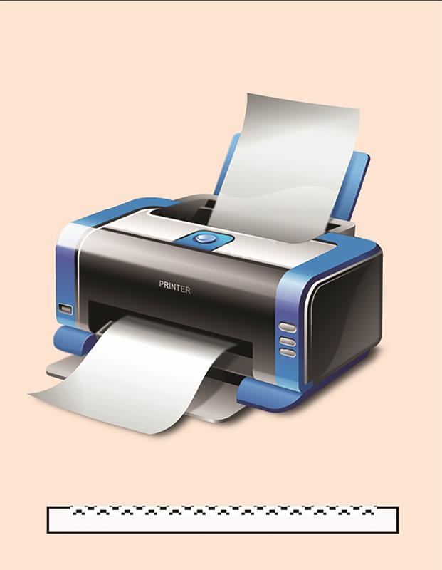 Figure 1a
However, one could also print on acetate sheet as teachers used to do in the days before PowerPoint and similar drawing aids. In this case, the acetate sheet does not absorb the ink, which instead sits on top of the acetate and, of course, can be overprinted several times. Each print building up the thickness of ink on the sheet (figure 1b).
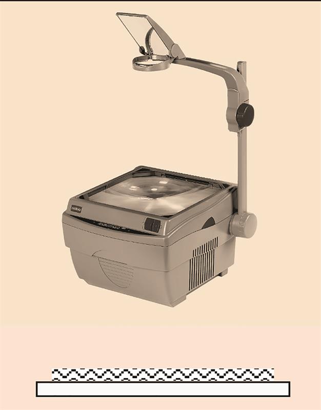 Figure 1b
Exactly the same process can be used for printing a spectacle lens. In the case of a plano-convex lens it would be built up as shown in figure 2, each layer being a fraction less in length that the previous layer and is seen to build to make the profile of a convex surface.
The same process can be used to build up a concave surface, now leaving an ever-increasing gap between the centre and edges of the surface with each layer.
The ‘ink’ that is used is a plastic monomer, one of which is similar to MR 6 in its optical properties – an HDDA (1.6-hexanediol diacrylate) capable of rapid cure when exposed to ultraviolet radiation. Each layer of ink is sprayed in the form of micro-droplets the size of which is only about 20 micrometres (microns) with a volume of just six picolitres. It will be appreciated that if each droplet is only 20 micrometres, a one millimetre thick layer of deposition requires 50 layers of ink. Each layer must be cured after each deposition.
The reduction in the length of each layer depends upon its position in the build up of monomer. In the case of a plus lens, each layer is about two micrometres smaller than the previous layer at the commencement of the deposition, the difference increasing to about 30 microns near the pole of the surface.
The first company to market a 3D printer specifically for spectacle lens production and, of course, all the technology required to manufacture the lenses, Luxexcel, is based in the Netherlands. At present, its equipment permits four lenses per hour to be produced. You can see more of their current offerings on their website, www.luxexcel.com.
Figure 3 shows their 3D printing equipment, the VisionPlatform, a single machine that offers a full production run in one piece of equipment.
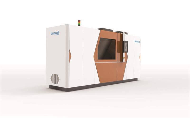 Figure 3: Luxexcel Vision Engine 3D printing system
The process, developed by Luxexcel, begins with the custom lens design and surface prescription being prepared in Luxexcel’s VisionMaster Software. The original monomer employed by Luxexcel was a liquid material, called VisionClear. It has a refractive index of 1.53 and Abbe No 45. The software is loaded into the VisionEngine 3D printer, which creates lenses by jetting tiny droplets of the UV-curable resin onto the substrate and curing it with UV radiation. This method produces lenses with less material waste. It is envisaged that smaller versions of this equipment will be developed enabling eye care practitioners to 3D print lenses in their own practices.
There is a growing demand to merge vision correction with other wearable technology. Combining these produces so-called smart glasses and is a huge untapped opportunity for both consumers and the wearable technology industry. Through the use of augmented reality (AR), data can be presented on displays built into spectacles or headsets. For example, one can obtain directions when out walking or driving in a similar fashion to that provided by a sat-nav, or superimpose instructions for the steps necessary to replace or repair an unfamiliar machine component, provide recipes and talking points for a presentation – all without holding a device or looking down at a screen.
3D printing technology is the easiest solution to produce lenses that combine a prescription correction with integrated embedded foils. The foil is not a lamination but is completely encapsulated inside the prescription lens material. This method is ideal for the new generation of prescription eyewear and smart glasses. Other examples of smart spectacles include electrochromic lenses that activate at the wearers demand by tapping the sensor on the side of the frame.
Switchable power lenses might also be constructed where there is a power change across the whole lens or just in the lower part of the lens in the form of a wearer activated bifocal segment when near vision is required.
Spectacles have been passive devices for decades. With the integration of technology, they would become interactive. The wearer will have one single product with multiple functionalities, potentially even replacing the need for smartphones. To create smart glasses, the two emerging trends of customising prescription lenses and integrating technology can be combined.
Many forms of smart glasses send an image to be overlaid on the image coming from the real world. To do this it is necessary to change the direction of light beams coming from one side of the frame so that it ends up in front of the visual axis. One way to do this is by creating an optical surface that directs the light through the interior of the lens where it encounters an embedded device, for example, a slanted diffraction grid that modifies the trajectory of light into the pupil. A unique feature of the 3D printing process of prescription lenses is that optical surfaces can be created not only on the front and the back but also on the side, which allows the light source to be integrated with the front of the frame rather than in the temples.
Increased prescription accuracy
A further development to be expected is an increase in the prescription and supply of lenses, not in quarter-dioptre steps, but in one-hundredth dioptre power intervals. Freeform machining methods produce a surface finish that is so smooth the surface can be polished immediately, the smoothing operation is eliminated and only some eight different polishing tools are necessary to finish the surface. Because ranges of smoothing and polishing tools are no longer necessary it is possible to produce lenses accurate to one-hundredth of a dioptre in any refractive index material.
It is this improvement in the manufacturing process that allows the laboratory to produce lenses with this accuracy and for instrument manufacturers to introduce sight-testing equipment capable of measuring the refraction to this high degree of accuracy.
Various major manufacturers have introduced autorefractors combined with other technologies such as a wavefront aberrometer, corneal topographer and keratometer all incorporated in a single device, three of which are illustrated in figure 4.
Figure 4: Various autorefractors/aberrometers capable of measuring in small increments of power
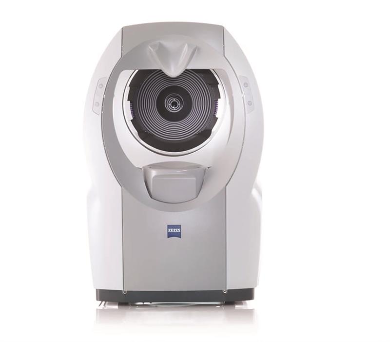 a) Carl Zeiss Vision i.Profiler plus
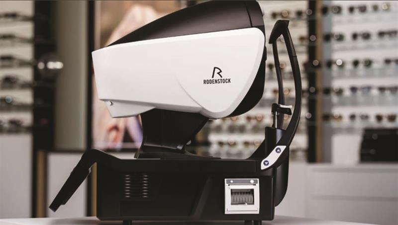 b) Rodenstock DNEye Scanner
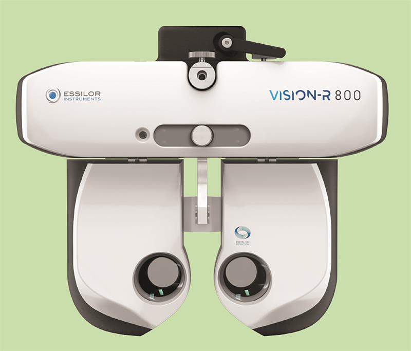
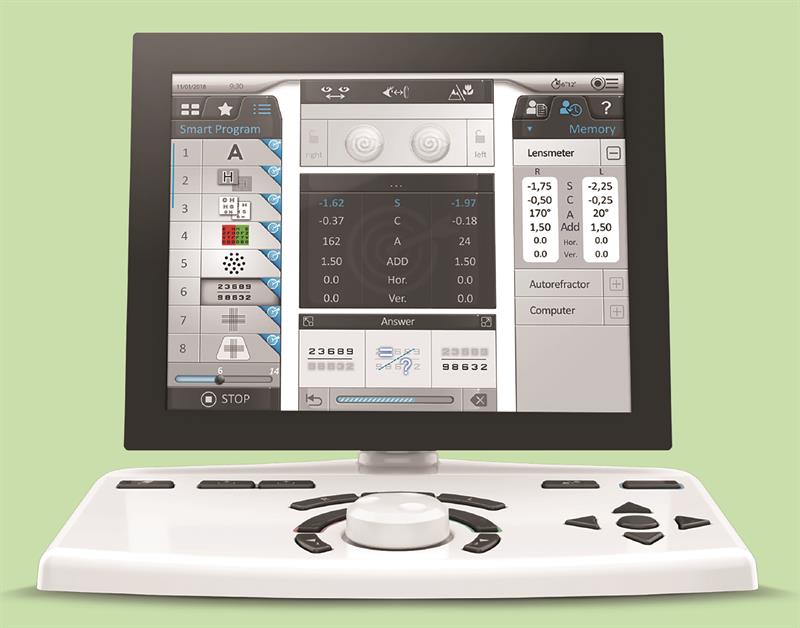 c) Essilor Vision R 800 system showing the phoropter unit and control console
The i.Profiler plus by Carl Zeiss Vision is a four-in-one compact system that combines an ocular wavefront aberrometer, autorefractometer, Atlas corneal topographer and keratometer in a single device. The refraction data is submitted to Carl Zeiss Vision, together with the measured values of the i.Profiler plus.
The Rodenstock DNEye Scanner is a combination of wave front aberrometer, autorefractor and corneal topographer. The scanner measures the eyes both for distance and in near vision. It also ascertains the higher order aberrations of the eye. The technology is claimed to offer the wearer razor-sharp and high-contrast vision, particularly at twilight. Lenses can be produced with an accuracy of 0.01 D via the Eye Lens Technology (EyeLT) software.
Essilor’s Vision-R 800 instrument offers subjective refraction in 0.01D steps to provide greater accuracy thanks to a patented, automated optical module powered by digitally-controlled motors. The device provides simultaneous and instantaneous changes of sphere, cylinder and axis to reach the final prescription faster, instead of examining these components individually.
Mo Jalie is visiting professor at the University of Ulster