
Last time, we discussed patient set up. Before starting to look at scanning options, there are a couple of further points worth remembering about set up. Both relate to ametropia which, if not prepared for, can lead to error when scanning
How do I adjust for high ametropia?
To get the best focus of image, we discussed last time the importance of selecting the mean sphere correction on the OCT (figure 1, red circle). There are two common refractive errors which need to be considered as potential sources of scan inaccuracy:
- High astigmatism; uncorrected cylinder can be compensated for by selecting focus based on the mean sphere. However, for larger cylinders, this results in the OCT image during the scan displaying at a tilt (figure 2a). The OCT image should be as level as possible in the active screen. When there is a tilt due to misalignment, normally you simply move the joystick sideways and the image rights itself. However, when the tilt is due to a cylinder, you need to change the angle of the scan direction. On the Spectralis, this is easily done by clicking and dragging one end of the blue scan line to rotate its orientation until the active scan is horizontal (figure 2b). The amount of reorientation will depend on the size of cylinder
- High myopia; as axial length increases with myopia, there is a tendency for the OCT cross section to appear bowed (figure 3), and in some cases a second reflected scan can enter the OCT window. Obviously, the first step is always to enter the mean sphere to ensure the image is as in focus as possible. If the image is still bowed, or if the retinal view is unevenly bright, you should use whatever adaptations your machine has. On the Spectralis, clicking on the ‘myopia’ tab (figure 4) drops down a menu that allows moderate scan adjustment (for around > -4.50DS) and higher myopia adjustment (for > -8 or -9.00DS). And remember; patients of > -12.00 DS ideally should wear contact lenses during the examination.
Further preset modification will be discussed in a future casebook when we look at more challenging patients.
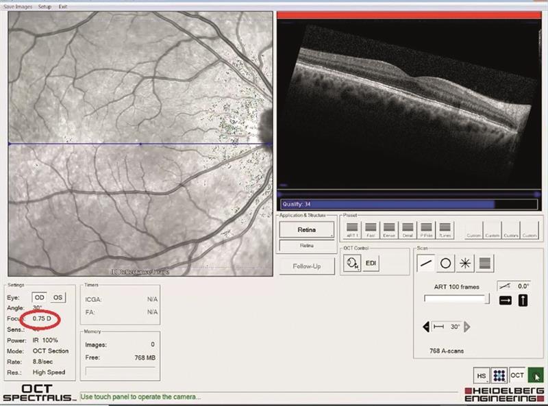 Figure 2a
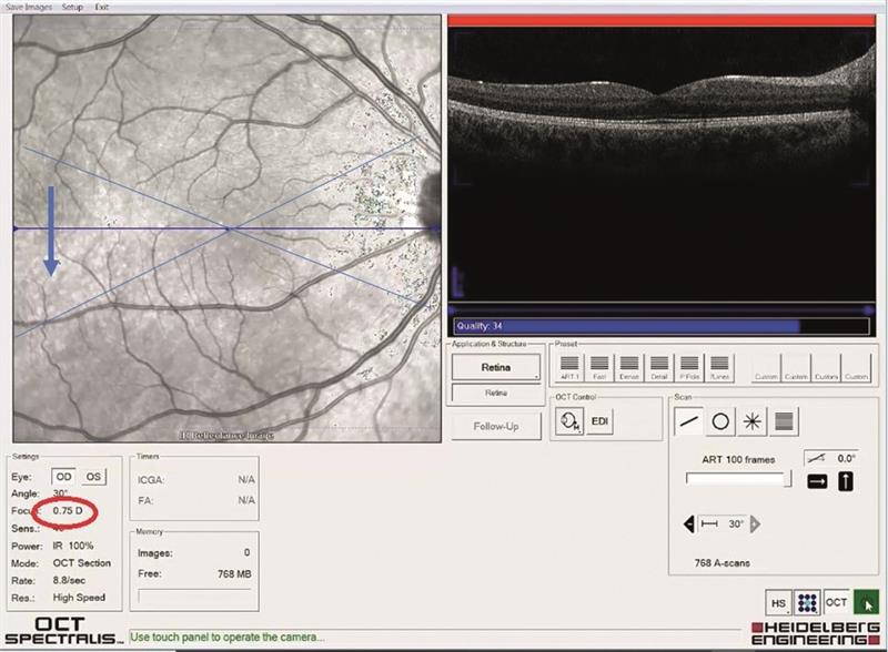 Figure 2b
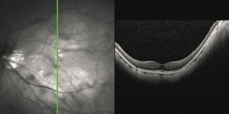 Figure 3
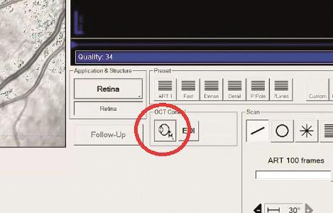 Figure 4
Which of the many scans should I use?
This is a topic we will keep revisiting, and by now you will have discovered that, whatever OCT you have, the scan option choice is sometimes bewildering. So, last time I suggested taking baseline OCT data from every patient at first visit. After much practice, and some discussion with our OCT professional support, my colleagues and I adopted a policy of always starting with two retinal and one glaucoma/disc scans, namely:
- Single line scans; one horizontal and one vertical (figure 5a) sweep of the laser giving a single cross section of retina, usually centred upon the fovea
- One volume scan; this is a scan where the laser sweeps across the retina many times, giving multiple cross sections (figure 5b), that can then be interpreted as a 3D ‘block’ of retina
- One retinal nerve fibre layer (RNFL) scan; a ring scan around the outside of the disc giving a circular cross section (figure 5c)
We felt that this offered a good general overview, but if anything of concern was revealed, or indeed if there was any prior knowledge of specific patient disease or risk, then other specific scans would be better. This, I hope, will become more obvious when we start to look at some case studies later in the series.
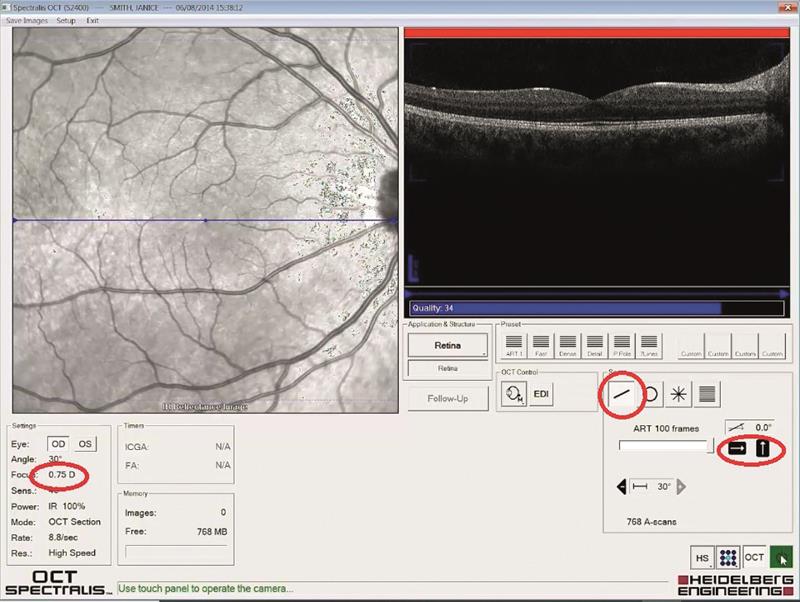 Figure 5a
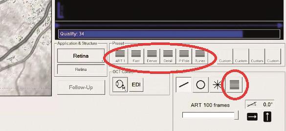 Figure 5b
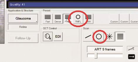 Figure 5c
Why a line scan?
OCT allows you to view a cross section through the ocular structures and the resolution possible with modern instruments offers impressive detail. It is, for example, possible to make out the individual layers of the retina. The default setting requires the patient to stare at a central fixation point and a single scan may then be taken, on the Spectralis by the click of a button (figure 6a). The horizontal scan is usually the default. Once completed, clicking the vertical line button switches to the vertical scan (figure 6b)
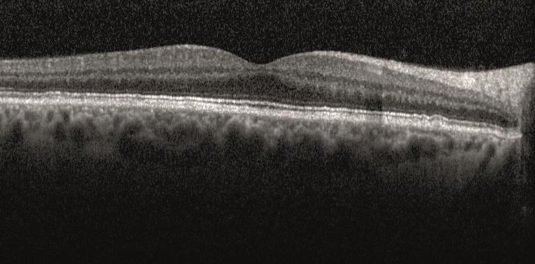 Figure 6a
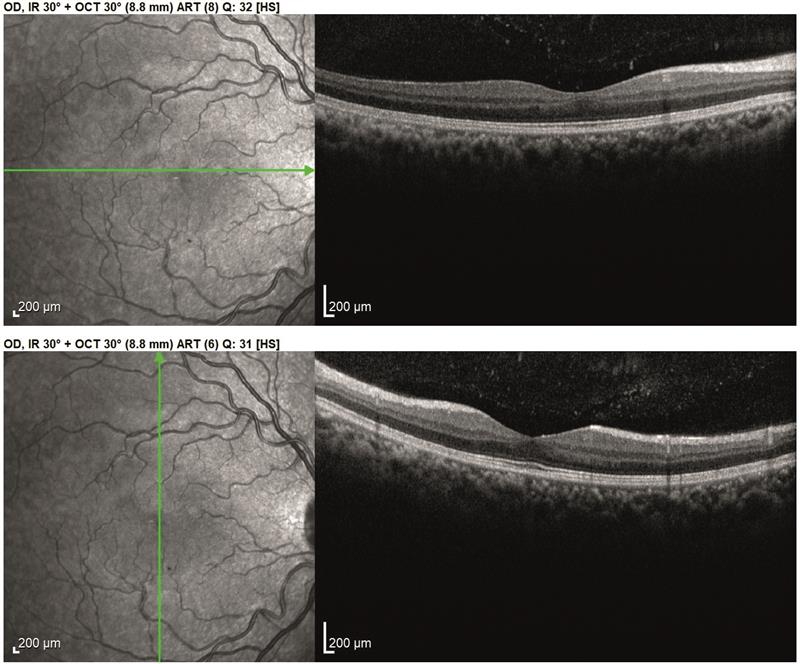 Figure 6b
By making a number of identical single sweeps, the software is able to add together sweep data and build up a much more detailed cross section image. The higher the number of sweeps and the better the software is at ensuring each sweep is taking data from the exact same position, then the better the detail of the final composite scan. On the Spectralis, the default is for 100 sweeps and this is initiated by holding down the button for a couple of seconds instead of a click. This switches on the tracking, whereby each subsequent scan is only accepted when exactly matching the position of the preceding one (more on this in future casebooks). During the process, live images of the retinal view and the cross section as they are scanned appear, and a scale shows how the 100 scans are progressing (figure 7a). The greater the scan number, the longer the process. The poorer the fixation, the longer the process. The greater the scan number and the better the tracking software, the greater the detail of the final cross section (figure 7b).
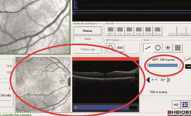 Figure 7a
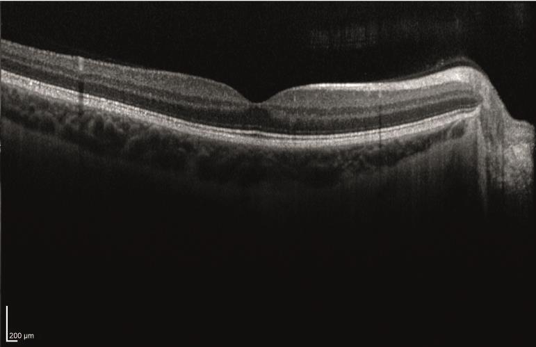 Figure 7b
As we shall soon see, the simple line scan is able to reveal much about the thickness of structures and the impact upon them of disease processes otherwise hidden from other imaging methods. Figure 8 shows a couple of visually impaired patient scans.
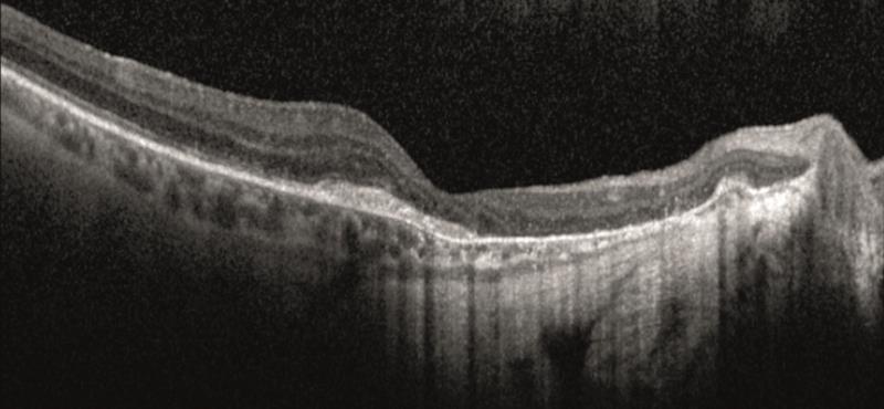 Figure 8a
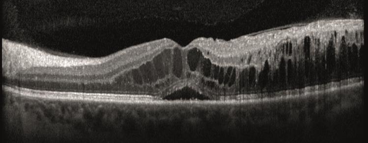 Figure 8b
In the next casebook, we will take a look at volume scans and the RNFL scan.
- The material presented in these casebooks is based upon use of the Heidelberg Spectralis but is designed to cover generic principles. Individual details of scanning and data presentation will differ depending on your OCT. The author and colleagues have no commercial interests in Heidelberg Engineering.