Fifth generation progressive designs
In 1995 there was a major breakthrough in progressive lens design. A patent1 was granted to Carl Zeiss for a new concept in which a progressive lens could be optimised for each individual prescription by combining a concave aspherical or atoroidal surface with a convex progressive surface in order to restore the optical performance to all powers within the range for which the convex surface had been designed. As an example, the prescription, +5.00 add +2.50 D might be made as a progressive lens with a convex progressive surface whose base curve, +8.25 D, has been specifically designed for this power, with the result that a contour plot of the iso-astigmatism lines is as shown in figure 1(a). The iso-astigmatism plot shows that the design has a wide distance area, a central corridor which is free from Minkwitz astigmatism leading to a fairly wide near zone.
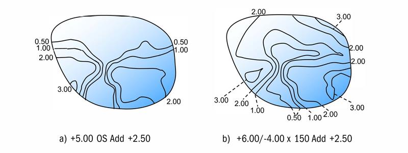
Figure 1: Iso-astigmatism plots for optimised and non-optimised designs, +8.25 base, add 2.50
In order to reduce the number of semi-finished blanks which must be kept in stock to produce a progressive lens range, it might be suggested by the manufacturer that this surface could be used for any prescription within the range +4.00 D to +6.00 D sphere. Of course a cylinder power within the manufacturer’s suggested range might also be required.
Suppose that this semi-finished blank is used to produce a power at the limit of the suggested range, say, +6.00 sphere with a -4.00 D cylinder with its axis at 150. The effect of working an ordinary toroidal surface with the curves -2.62/-6.62 with the axis at 150 is to cause a change in the overall iso-astigmatism pattern to that shown in figure 1(b).
Quite clearly, the iso-astigmatism lines now encroach into the distance portion area, especially along the 60° meridian, where the power of the lens is only +2.00 dioptres in the distance area. This value is far removed from the power +5.00 D for which the surface was designed. Along the 150° meridian where the power of the lens in the distance area is +6.00 D, the iso-cylinder lines are more widely spaced. The Zeiss patent suggested the concave surface should be produced in atoroidal form, with the asphericity of the surface specifically computed to restore the Minkwitz astigmatism to the same value and distribution as in the original power for which the surface was designed.
Essilor’s Varilux VisionPrint System
This breakthrough was made possible by the advent of free form generators and polishers in the middle of the 1990s, together with the advances in processing speed of the computers which could perform the necessary calculations in real time. It was the dawn of modern, free form progressive lenses. The patent also suggested that if the practitioner submitted fitting parameters, such as the vertex distance and the pantoscopic tilt, the software could custom design the lens for the individual specification. The ability to optimise a progressive lens in order to produce wide distance and near zones together with a corridor of reasonable width for any prescription, even in the case of prescriptions with an oblique cylinder, was designed to eliminate adaptation problems for most progressive lens wearers.
Zeiss introduced its new lens as the Gradal Top with Optimum Surface Design (OSD), known in the USA as the GT2 design. Almost at the same time, Rodenstock introduced its own optimised progressive lens called the Multigressiv.
During the first five years of the new millenium, enormous strides were made in the development of CNC production technology, leading to modern surfacing techniques that are now generally known as digital surfacing or free form production methods. At the same time, computer processing speed had increased sufficiently to make it possible for the software to design the surface in real time, in other words, at the time that the surfacing laboratory received the prescription order. The design procedure is illustrated in figure 2.
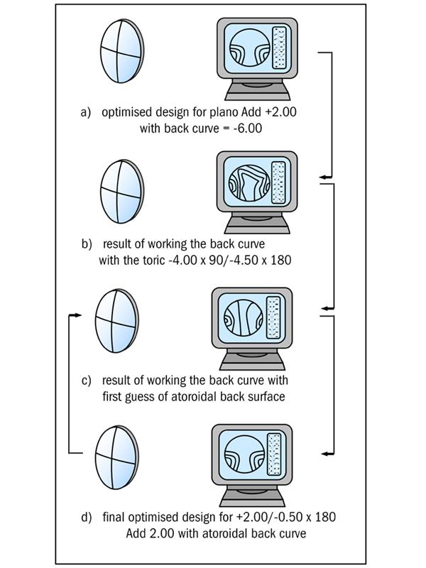
Figure 2: Optimisation routine for a progressive lens
Suppose that an order is received by the laboratory for a progressive lens with an addition of +2.00 D, to the specification, +2.00/-0.50 x 180, for distance vision. The lab might pick a semi-finished blank with a +5.87 D base curve, whose progressive surface was designed to be used for the prescription, plano add +2.00. The optimisation software will draw on files which describe the progressive surface by its (x,y,z) co-ordinates. If the prescription, plano add +2.00, had been ordered, then the back surface would simply be worked with a -6.00 D curve, and the plot of the iso-astigmatism contours would be regular, with the lens having a wide distance zone, the progressive corridor well positioned, and a wide near portion in the correct position as illustrated in figure 2(a).
The software now adds the actual back surface which will provide the correct prescription, in this case, -4.00 DC x 90/-4.50 DC x 180 and analyses the result by tracing rays of light through this combination of surfaces. The designer will have assigned optimisation criteria, often described as merit functions, to various regions of the surface and as a result, the mean power, astigmatism and axis direction calculated at many points across the surface. If no correction has been made to the surface the results of the first ray trace might be as shown in figure 2(b).
Clearly, the first guess at the geometry of the back surface does not produce the desired result, the software will recognise that the merit functions with which it has been provided have not been satisfied, and it will modify the back surface and trace through the second guess at the surface to obtain the results shown in figure 2(c). The optimisation procedure will continue until the desired result shown in figure 2(d) is obtained.
In the year 2000, a patent2 was assigned to Johnson and Johnson for a progressive lens which shared the near addition between both surfaces, so that each surface was progressive. They claimed the invention provided for progressive addition lenses in which unwanted astigmatism is reduced, and the channel width through the intermediate and near vision zones is increased, compared to conventional progressive addition lenses. Their reasoning was based upon the fact that the lower the addition, the wider becomes the intermediate and near areas, as depicted in figure 3(a). The small crosses in the lateral areas of the intermediate portions depict the points on the designs where the Minkwitz astigmatism reaches its maximum value.
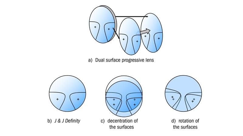
Figure 3: Dual surface progressive lens, Johnson & Johnson Definity
By reducing the addition provided by each surface, and decentring the surfaces in relation to each other, the areas where the surface astigmatism reaches a maximum would be shifted, thereby reducing the maximum astigmatism exhibited by the lens. The maxima can be shifted either by decentring one surface in relation to the other (figure 3(b)), or, by rotating one surface in relation to the other as shown in figure 3(c). The new point of maximum astigmatism now lies between the two crosses and is smaller than the value obtained before separation. Johnson and Johnson marketed their new design in the United States for a few years as the Definity design, but eventually sold the technology to Essilor.
In 2000, Essilor introduced their fifth generation design the Varilux Panamic which was claimed to retain all the benefits of Varilux Comfort and achieve an even smoother surface topography in the periphery of the lens. This enabled the design to address the comfort of the overall field of vision and provide a significant improvement in the overall effect of the lens in wear. Essilor described the enhanced performance of the Panamic design as global vision. What was meant by this term was that, since the change in mean power and astigmatism across the surface was so smooth, movement in the periphery of the visual field could be easily identified and clear vision would be possible as soon as the object moved into the field of fixation. The criterion for a best form spectacle lens is that it should produce a good quality image on the fovea. Providing the distortion produced by the correcting lens is not excessive, and particularly, not significantly different from the distortion to which a subject has become accustomed from a previous pair of spectacle lenses, the brain interprets the scene as rectilinear. It has already been pointed out that, in most cases, the brain adapts easily to small changes in distortion.
If the magnification produced by the lens in the peripheral field is irregular, due to rapid changes in the shape of the surface, peripheral objects will appear to change direction. This is often described as a swimming effect by the new wearer of progressive lenses, as images viewed through peripheral portions of the right and left lenses apparently move at different speeds. The swimming effect is a combination of distortion produced by the increasing power between the distance and near portions, and changes which take place in surface topography as the result of trying to achieve the correct blend between the various zones of the lens. The influence of distortion is summarised in figure 4.
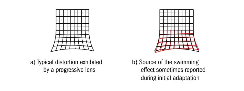
Figure 4: The swimming effect resulting from lack of correspondence of monocular fields
In the case of progressive lenses, the power of the lens increases from distance to near by the value of the addition. There is an accompanying increase in magnification, as shown in Part One, which causes vertical lines viewed through the progression zone to slant. In designing the Panamic lens, Essilor developed a new ray tracing system which gives the position in space of the various components of the visual scene. A net, rather like the object shown in figure 4(a), was superimposed upon the visual scene and the positions of the intersections of the net in the image space calculated by ray tracing through the lens. The positions of the images produced by the right and left lenses were calculated, and by superimposing the two images, an indication of the relative speed difference between the movement of the right and left images in the peripheral field obtained when the eyes rotate to view various parts of the scene.
The effect can be visualised from figure 4(b) where the field obtained with one eye through the progression and near zones is illustrated in black, and the field obtained with the other eye shown in red. Ideally, as the eyes rotate behind the lenses, the two fields should correspond exactly to form the binocular image. If the fields do not coincide, as depicted in the figure, and what is worse, if the separation increases and decreases as the eyes roam to use different zones of the lens, the scene appears to swim. The real breakthrough which was claimed for the Panamic design, was the reduction of swim effects in progressive power lenses, obtained by ensuring that although the power increased steadily from the progression zone to the near zone along the meridian line, it reduced significantly in the peripheral portions of the lens.
Until the end of the 20th century, with the exception of the Essel Variplas designs of the 1960s, the progressive power was generally incorporated on the convex surface of the lens. This enabled the finishing laboratory to work any cylinder on the concave side using their normal surfacing machinery, and without the need for a large range of plus base toric tools with compensated cylinder powers. In 1996, a patent was applied for by H Mukaiyama and K Kato of the Seiko Epson Corporation of Japan (the US Patent was granted in 20003) for a progressive lens which had a concave surface, which incorporated both the progression and any correction for astigmatism. The convex surface of the lens was a simple spherical or aspherical surface and the concave surface was either a progressive power surface, in the case of spherical prescriptions, or a progressive surface of atoroidal form in the case of astigmatic prescriptions (figure 5).
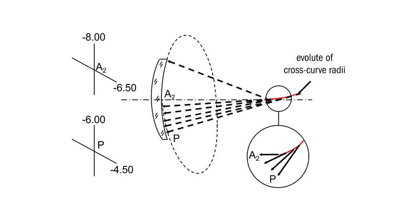
Figure 5: Evolute of cross-curve radii for a lens with a concave progression surface
A typical concave progressive surface is described in the patent by its (x,y,z) co-ordinates and, in theory, the surface could be manufactured by programming the CNC generator to reproduce these points. The surface, described by its (x,y,z) co-ordinates, rather than by a single mathematical equation, is a free form surface. The patent discusses the advantages of having a spherical convex front surface in that the shape factor component of the spectacle magnification is the same in both the distance and near portions, whereas with a convex progressive surface, the shape factor will increase as the front surface power increases between the distance and near portions. A small increase in the field of view is also claimed because the progressive surface lies closer to the eye when it is positioned on the back surface of the lens. Seiko originally marketed this lens as the P-1SY Grand Genius progressive design and has made the software available for any surfacing laboratory to be able to purchase and produce its own free form, progressive surfaces. It is not clear from the patent whether the surface is optimised for any prescription or whether the process described simply adds the progressive height data to that of the toroidal surface.
A similar patent was assigned to Carl Zeiss4 in 2000 for a progressive lens with a spherical front surface and combined toroidal and progressive surface on the concave side of the lens. However, this design is also optimised for each individual prescription. The iso-astigmatism and mean power error plots shown in figure 6 should be obtained for any prescription. The Zeiss software permits full individualisation of each lens when all the fitting data, vertex distance, pantoscopic and, face form angles, etc, are supplied on the prescription order form. The lens was introduced as the Gradal Individual. Note that the iso-mean power error plot shown in figure 6 indicates the areas of the lens where the power is deficient in some way.
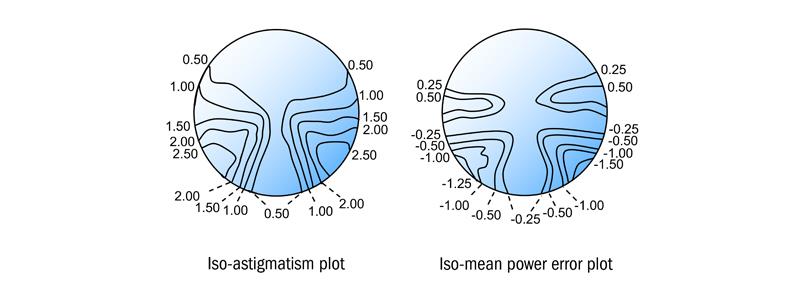
Figure 6: Iso-astigmatism and mean power error plots for Zeiss Gradal Individual
It has been seen that most fifth generation progressive lens designs had a convex progressive surface and a concave prescription surface. Hoya’s fifth generation design was a complete departure from the norm, in that it employed a bi-toric construction in order to achieve the full near addition. The vertical component of the addition is incorporated on the convex side and the horizontal component on the concave side of the lens. Consider the usual form of progressive lens which has a convex progressive surface and the final prescription is produced by working the concave side shown in figure 7(a). It can be seen that the power on the convex progressive surface increases from +5.00 D in the distance zone to +7.00 D in the near zone along both the 90 and 180 meridians. Then, to produce the specification, plano add +2.00, it is necessary to work the concave surface with a nominal -5.00 D sphere curve. When the effect of each lens surface is considered upon an incident narrow beam of light, it can be seen that, by adding together the surface powers both in the vertical meridian, and then in the horizontal meridian, they neutralise one another, resulting in a distance zone of zero power.
Similarly in the near zone we see the effect of the lens in both vertical and horizontal meridians is +2.00 D, as is required to obtain the near portion power.
In the case of the Hoyalux iD Integrated Double Surface progressive design5 shown in figure 7(b), the full reading addition is obtained by incorporating the vertical component of the addition on the convex surface and the horizontal component on the concave surface. It can be seen in figure 7(b) that the convex surface increases in power from +5.00 D to +7.00 D along the vertical meridian, but there is no change in power between distance and near along the horizontal meridians in the intermediate and near zones, which remains +5.00 D. Since the back surface is also -5.00 D along the vertical and horizontal meridians in the distance zone, this area of the lens has zero power.
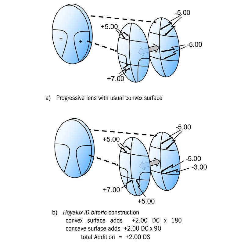
Figure 7: Iso-astigmatism and mean power error plots for Zeiss Gradal Individual
Now considering the near zone, the power in the vertical meridian on the convex side is +7.00 D and the power on the concave side in the vertical meridian is -5.00 D, hence, along the vertical meridian there is an increase in power of +2.00 D from the distance portion. In the horizontal meridian, the power on the convex side is +5.00 D and the power on the concave side in the horizontal meridian has changed progressively to -3.00 D. Hence, along the horizontal meridian, there is also an increase in power of +2.00 D from the distance portion. The total near addition is made up from +2.00 DC along the vertical meridian of the front surface of the lens and +2.00 DC along the horizonal meridian of the back surface of the lens, which provides a spherical addition of +2.00 DS. The patent explains the lens could be made from scratch once the prescription order has been received by the laboratory, but it is advantageous to produce semi-finished blanks with the convex surface finished to a particular base curve and vertical near addition component so that the prescription surface can be completed after receipt of the order from the practitioner.
Suppose that a semi-finished blank has been worked with a convex progressive surface which has a +5.00 DP curve and a +2.00 D addition along the 90 meridian as shown figure 8. In order to produce the prescription -3.00/-1.00 x 180 the back surface would be worked with the curves
-8.00 x 90 / -9.00 x 180
in the DP area of the concave surface.
In the near portion, the lens already has the curves
+5.00 x 90 / +7.00 x 180
worked on the front surface and so to make up the near prescription, the curves
-6.00 x 90 / -9.00 x 180
must be worked in the NP area of the concave surface (figure 8).
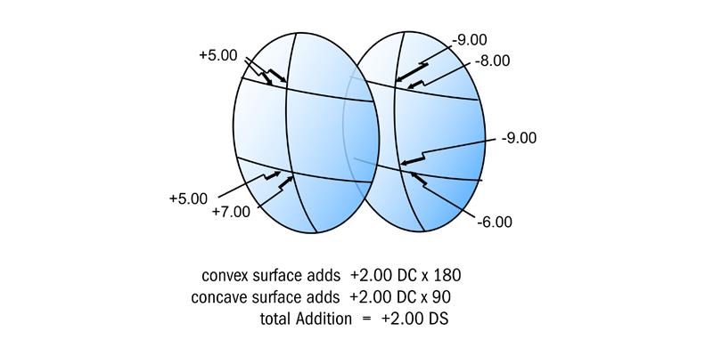
Figure 8: Surface powers for Hoyalux iD made to the prescription -3.00 / -1.00 x 180 Add +2.00
Instead of using the usual contour plots to illustrate the performance of the Hoyalux iD family of lenses, Hoya has introduced a Clearness Index. This is arrived at by tracing more than 100 rays of light through the pupil for all zones of the lens, the rays emanating from points in space identified to the computer by its (x,y,z) co-ordinates. After passing through the lens into the eye, each ray will strike the retina to form a spot diagram, from which an encircled energy plot enables the computer to determine a point spread function, from which it can determine the likely reduction in visual acuity which will result. A typical Clearness Index for a plano add +2.50 Hoyalux iD design is shown in figure 9.
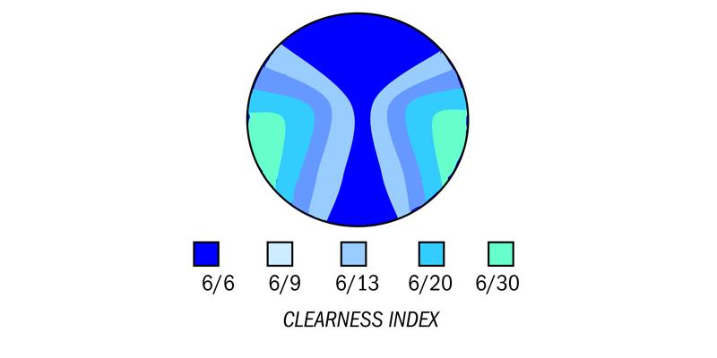
Figure 9: Hoya’s Clearness Index plot
In 2004, following research undertaken at the University of Montreal6 a new lens was introduced by Essilor which took into account the actual degree of head and eye rotation which the wearer employs when viewing through the intermediate and near zones of the lens. The research had shown that each individual has a specific head and eye behaviour that can be measured, and the progressive surface then designed to incorporate the wearer behaviour. This principle has been incorporated into the personalised progressive design from Essilor, the Varilux Ipseo.
Figure 10 illustrates the visual point positions on the lens for two successful progressive lens wearers, denoted A and B. The positions of the visual points were measured when each wearer was asked to identify targets which appeared at random in the intermediate field of view. Wearer A is quite clearly an ‘eye-turner’ who perceives objects quite clearly over a wide zone of the lens. Such a wearer would claim the width of their intermediate field was as wide as the lens itself. Wearer B, on the other hand, tends to ‘point-the-nose’ at objects in the intermediate field and, for whatever reason, prefers not to view through peripheral parts of the lens. The method of determining this characteristic is shown in figure 11. The relative movement of the head is detected by sensors attached to the head when the subject is asked to view an object in lateral portions of the field. Knowledge of this characteristic can help the practitioner to choose the best progressive design for a new wearer of progressive lenses.
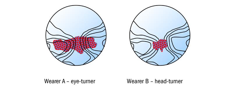
Figure 10: Comparison of visual point positions for ‘eye-turner’ and ‘head-turner’
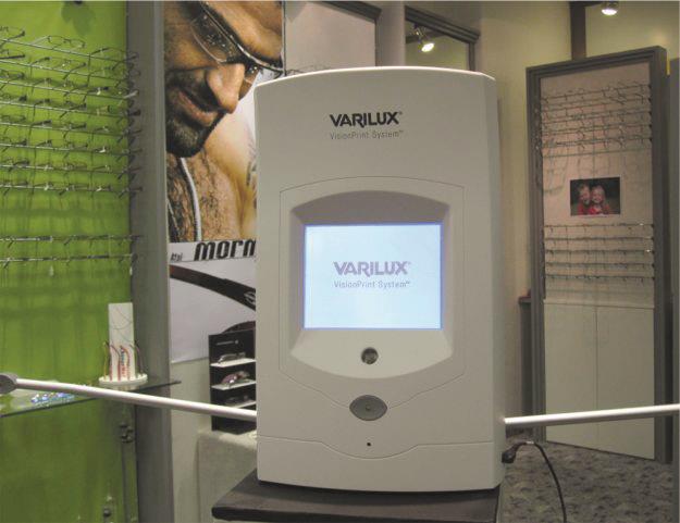
To assist the practitioner, a new instrument was introduced to determine eye/head movement for a specific individual, the VisionPrint System, the results from which can be incorporated into the progressive surface. Essentially, the VisionPrint System consists of three lamps, the central lamp is viewed at 40cm from the centre of the subject’s forehead, with two separate lamps, 40cm on either side of the central lamp. The subject is directed to look at the lamp which is illuminated and the movement of the head is recorded by an ultrasonic signal emitted by the system and reflected by a transponder attached to the special trial frame being worn by the subject. As far as the subject is concerned, the lamps are illuminated at random and following a short cycle to familiarise the subject, the test sequence is repeated some 20 times to enable the system to calculate and display the eye/head ratio, along with a consistency factor, referred to as the stability coefficient.
In order to quantify the relative eye/head movement, a variable is used which is called the ‘gain’ and is equal to the ratio of the angular movement of the head to the total angle of the target:
Gain = (head angle) / target angle
Thus, if the target angle is 45° and the head rotates 15° to view the target the gain is 0.33. Clearly a gain of zero would indicate the subject was an eye turner, whereas a gain of 1.0 would indicate that the subject was a head turner. People who tend to turn, mainly, their heads when viewing lateral objects will benefit from a design which provides optimum central acuity, ie a softer design, whereas people who tend to turn mainly their eyes, will benefit from a design which provides good acuity over a wider field, ie a harder design. The VisionPrint system enables the practitioner to determine the wearer profile of the individual quickly and accurately, and provides a method for communicating the information to the laboratory for incorporation in the design of the surface. Thus, Essilor could claim that each Varilux Ipseo lens is designed for the individual wearer, manufactured by freeform technology, and, in recognition of its individual nature, micro-engraved with the wearer’s initials.
Rodenstock introduced their original Multigressiv design in 1995. With Multigressiv 2 came online optimisation of the concave surface with an aspherical surface being applied to spherical prescriptions and an atoroidal surface being used when the prescription calls for a cylindrical correction. Manufacture of the concave surface of the lens began when all the prescription data was to hand, the form of the atoroidal surface depending not only upon the base curve, but also the cylinder power, axis direction and the inset required for the lens. This technology required the development of software for rapid computation of the second side.
MultigressivILT applied Individual Lens Technology (ILT) to the design, enabling the optimum progressive power surface to be computed individually for each lens from knowledge of the prescription data and base curve of the lens. With this new design, the progressive surface was switched from the front to the back surface of the lens, which, in the case of astigmatic prescriptions, also incorporates the cylindrical correction. The front surface of the lens is a simple spherical surface, with the near addition and necessary aspheric correction for the form, being built into the concave surface. With astigmatic prescriptions, the concave surface is an atoroidal, progressive surface as illustrated in figure 5.
The personalised version of the Multigressiv design was introduced as the ImpressionILT lens. Just like the MultigressivILT, it has a concave progressive power surface which is combined with the cylinder in the case of astigmatic lenses, but it can also incorporate the precise positioning of the lens in its design. In addition to the individual CDs and progression heights, practitioners can submit the vertex distance, pantoscopic angle and the face form angle of the front. The face form angle takes into account the bow of the front of the frame. The computer software allows input of all the different fitting parameters as variables in deciding the optimum form of the concave surface, so the resulting lens is custom-designed for the individual fitting of the frame to the face.
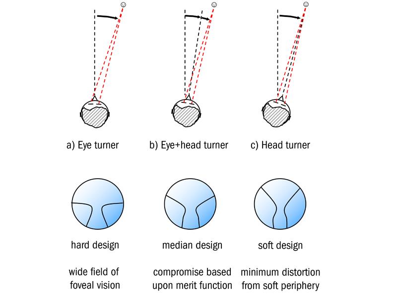
Figure 11: Progressive designs for ‘eye-turners’ and ‘head-turners’
The popularity of small, shallow-eye, spectacle frames encouraged several manufacturers to introduce short-corridor, progressive designs to ensure the subject had the benefit of their full near addition within the shallow lens area. One of the questions asked was ‘just how deep does the vertical box dimension of a spectacle frame need to be to ensure that the wearer had an adequate area for near vision?’. It had been noticed in particular that a shallow-eye frame had a ‘letterbox effect’ of requiring wearers to rotate their heads more to view through lateral areas of the lens and wearers of shallow-eye frames tended to lower the head more, reducing eye rotation in the vertical meridian. In 2004, Essilor introduced the Varilux Ellipse, a short corridor design which, they claimed, could be fitted into a frame with a minimum vertical box dimension of 24mm, provided there was a minimum distance of 14mm below the pupil centre to provide an adequate near vision field (figure 12).
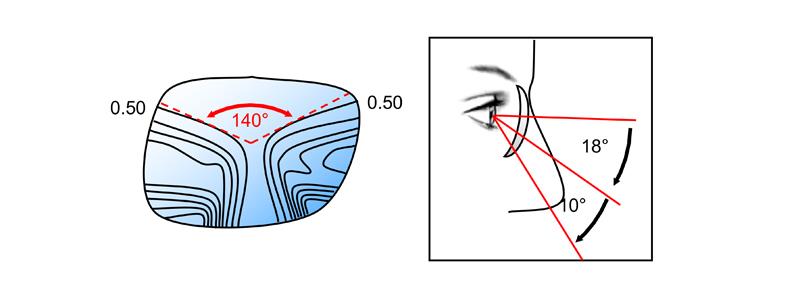
Figure 12: Hoya’s Clearness Index plot
Most of the major lens manufacturers introduced new designs at the turn of the 21st century, some rebranding earlier designs, others producing short corridor versions of their existing lenses in answer to the continuing popularity of small eyesize frames.
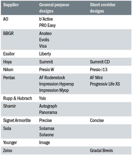
Table 1: Other fifth generation designs
Table 1 lists some other designs of the fourth and fifth generation, which are not specifically mentioned in the main body of the text.
Professor Mo Jalie is a visiting professor at Ulster University and author of the new edition of Principles of Ophthalmic Lenses.
References
1 Kelch G, Lahres H, Wietschorke H (1995). US Patent 544503, Spectacle Lens.
2 Menezes EV, Gupta A, Kokonaski W (2000). US Patent 6106118, Progressive Addition Lenses.
3 Mukaiyama H, Kato K (2000). US Patent 6049470, (Assigned to Seiko-Epson). Progressive Multifocal Lens Manufacturing Method of Eyeglass Lens and Progressive Multifocal Lens, Japanese application dated November 24, 1995.
4 Hof A, Hanssen A (2000). US Patent 6089713. Spectacle Lens with spherical front side and multifocal back side and process for its production.
5 Kitani A, Kikuchi Y (2005). US Patent 6935744, Bi-aspherical Type Progressive Power Lens. Assigned to Hoya Corporation. Original Japanese patent applied for in 2003.
6 Simonet P, et al (2003). Head-eye co-ordination in presbyopes, Points de vue 49, Essilor, Paris.