A second method by which an increase in plus power might be obtained with a fluid adaptive lens is to have a sealed chamber of biconvex form, which, by applying equal pressure all round its circumference, can be compressed into a more biconvex shape (figure 1). A recent development is the introduction of full aperture single vision lenses by the British Company, Adlens, whose power can be changed over a range of +2.50 D by fluid adaptive lenses. The lenses are intended to provide full distance vision correction, sphere, cylinder, axis and any prism which is incorporated in the outer components of the device, but the spherical power can be increased up to +2.50 D, at the subject’s will, by adjustment of a small knob contained in the joint of the specially made frame. Allfield spectacles, (originally known as Focuss spectacles but now rebranded) are described as Variable Power Optics, which provide a continuous range of intermediate and near vision additions up to 2.50 dioptres entirely under the control of the wearer. The initial concept was to provide an invisible full aperture multifocal design to those presbyopes who could not adapt to progressive lenses.

An interesting feature of the Allfield spectacles is that the shape of the adaptive lens is not circular (figure 2).

It is easy to understand that in the case of a circular lens, an increase in the volume of the fluid will cause the lens to swell equally in all directions, maintaining the shape of the surfaces. However, in the case of the oval-shaped lens illustrated in figure 3, since more fluid is required to take up the greater space in the horizontal meridian than in the vertical meridian, the surfaces will tend to become toroidal with the greater curvature in the vertical meridian.
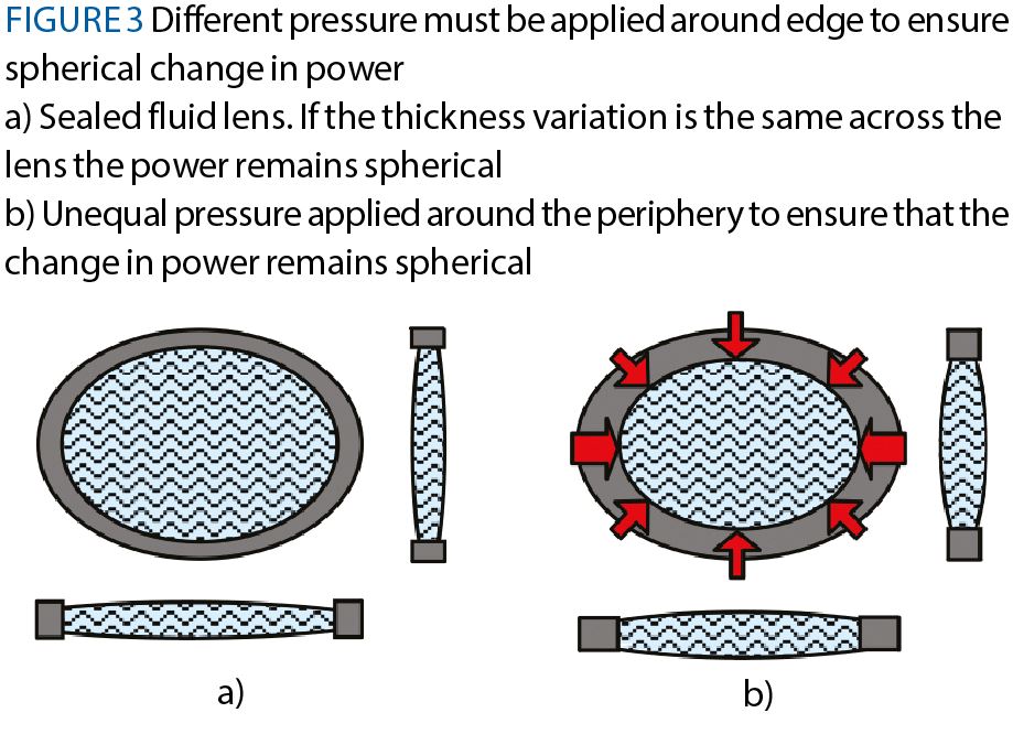
In order to maintain equal curvatures in each meridian, so that an increase in spherical power is generated without an accompanying cylinder power, greater pressure must be applied to the fluid in the horizontal meridian than in the vertical meridian, as shown schematically in figure 3b.
The calculation of how the pressure differential must be made to vary in order to provide a change in spherical power across the major portion of the lens, is just one of the novel features incorporated into the Allfield design.
The component lenses in the Allfield spectacles are shown in figure 4.
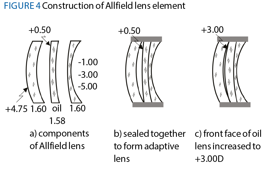
The outer elements of the lens are made from plastics material of refractive index 1.60 which is so close to the refractive index of the oil which is sealed into a very thin flexible plastics sac as shown in figure 4a, that when the sac is placed in contact with the rear plastics component, the interface has virtually no residual power. The front surface power of the first component, which is the prescription element, is typically +4.75 D and the back curve of the third element is selected by prescription from one of the three available curves, which were originally, -1.00 D, -3.00 D or -5.00 D.
The front surface of the oil filled sac is in contact with air behind the front component and is formed to have a front curve of +0.50 D in its resting state, which can be increased to +3.00 D by injecting more fluid into the sac. The control knob contained in the front lug of the frame allows a variable amount of oil to be injected by the wearer but also has two stop positions which allow 50% of the fluid contained in the reservoir to be added to the adaptive element to provide an intermediate add or the full content of the reservoir to provide a full addition of +2.50 D. Typically, the wearer would adjust the variable addition for the task in hand.
The prescription surface which is worked to provide the individual prescription is the back surface of the front element. Figure 5 illustrates the curves which would be employed for the prescription:
R -3.00/-1.00 x 180
L +2.00/-0.50 x 180.

Variable power lenses made from electro-active materials
Consider an optical material whose refractive index is 1.67, until an electric current is passed through the material, causing the refractive index to fall to 1.53. Then, when the current is switched off, the material regains its original refractive index of 1.67 (figure 6).

Such a material has been developed1 in the form of a cholesteric liquid crystalline material and has been used to produce electrically adaptive multifocal lenses. A simple way of understanding how the change in refractive index is brought about is to imagine that in its inactivated state, the molecules which make up the liquid crystalline material lie at right angles to the direction of the incoming light (figure 7a), thereby impeding its transmission through the material. Passing a current through the liquid crystalline material causes the molecules to flip through 90º (figure 7b) so that they now lie in the same direction as that of the incoming light. This action allows the light to pass more quickly through the material and since the refractive index is a function of the speed at which light travels through the material, effectively lowers the refractive index of the material in its activated state.

Cholesteric liquid crystalline materials are optically uniaxial and, therefore, birefringent, with an ordinary refractive index, nO, and an extraordinary refractive index, nE. However, in a cholesteric liquid crystal, the director rotates in a helical manner over the thickness of the material. The helical rotation of the director is characterised by an axis of rotation as well as a handedness, dextro-rotatory or laevo-rotatory, and a twist pitch. The twist pitch is defined as the length along the axis of rotation over which the director rotates through a full 360°. Optical waves having wavelengths comparable to the twist pitch and travelling in a direction perpendicular to the liquid crystal’s director, (ie polarised in the same direction as the director) will experience an average refractive index, nAVG, equal to (nO + nE)/2. Because the value of nAVG is substantially constant with respect to the polarisation state of the incident waves, the cholesteric liquid crystalline material is insensitive to the state of polarisation. In the presence of an electric field applied in a direction perpendicular to the alignment layer, most of the material’s directors align with the field, effectively unwinding the director of the helix. As such, a wave travelling along the director axis of rotation will experience a continuous and polarisation insensitive change in the value of the refractive index between the average value, nAVG, and the ordinary value, nO. If the electric field is strong enough, the directors of the cholesteric liquid crystalline material will be substantially parallel to the applied electric field, whereas a wave travelling in a direction perpendicular to the layer of material will experience a refractive index of the ordinary value, nO.
If the cholesteric liquid crystalline material is in contact with an alignment layer and no electric field is applied, the director of the material at the interface between the alignment layer and the cholesteric liquid crystalline material will lie in the same direction as the alignment direction. An incoming light wave which is travelling in a direction perpendicular to the material will experience a refractive index of nAVG. If sufficient current is then applied, the director will rotate through 90°, so that an incoming wave will experience a refractive index of nO.
One of the first applications of this technology in the ophthalmic field was introduced by Dr Ronald Blum 2,3 of Pixel Optics in the USA under the tradename, emPower. The effects of Minkwitz astigmatism and skew distortion increase with the near addition, thereby hindering wearer adaptation to progressive power lenses. Following research by a team of optometrists in the USA, it was concluded that, as a rule, the requirement for near vision was only some 20 to 30% of the day. For most daily activities, subjects required mainly distance and intermediate vision. Hence, in practice, use of the near portion of multifocal lenses or progressive lenses was restricted to only some 25% of the time that the spectacles were being worn. For most of the time, only the distance and intermediate zones were being used, and therefore, it was concluded, why not develop a lens where the near portion could be ‘switched off’ when not required?

EmPower design
The final lens design which came to the market was a progressive lens whose near addition was some 50% of the full near addition with an electro-active segment near the bottom of the lens which could be brought into use, simply by tapping the side of the frame. Since only 50% of the full addition was present for most of the time, the aberrations in the lower peripheral portions of the lens were greatly reduced and clear vision of the ground or steps at the wearer’s feet was not impeded by the presence of a full near addition.
The principle of the emPower multifocal lens design is shown in figure 8.

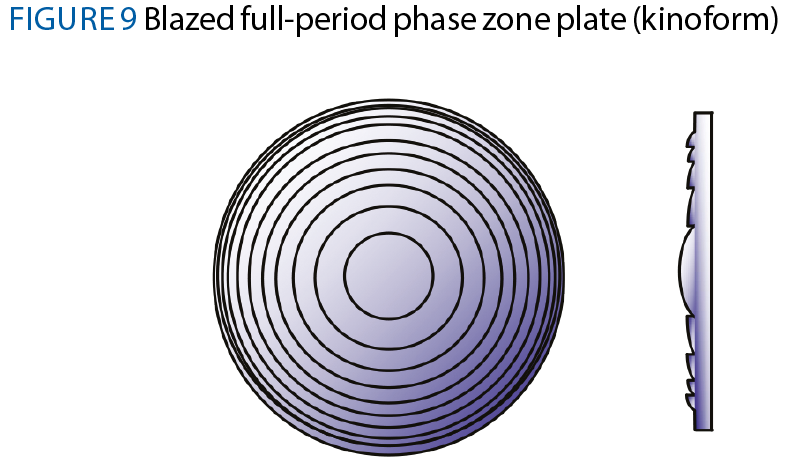
Since it is the near portion that requires to be switched on and off, and must have a lower refractive index than that of the main lens (the electro-active action is to cause a reduction in the refractive index of the material), the designers of the lens realised that a refractive segment element would not be practical and turned their attention towards a diffractive segment element, which can be produced in a very thin form. The diffractive lens is similar to an imaging Fresnel lens which is buried in the element in the form of a blazed, full period phase zone plate or kinoform (figure 9).
A full-period phase zone plate is simply a series of annular apertures the distances of which lie successively one more wavelength from some point P which lies at a distance d from the zone plate on its axis of symmetry (figure 10).
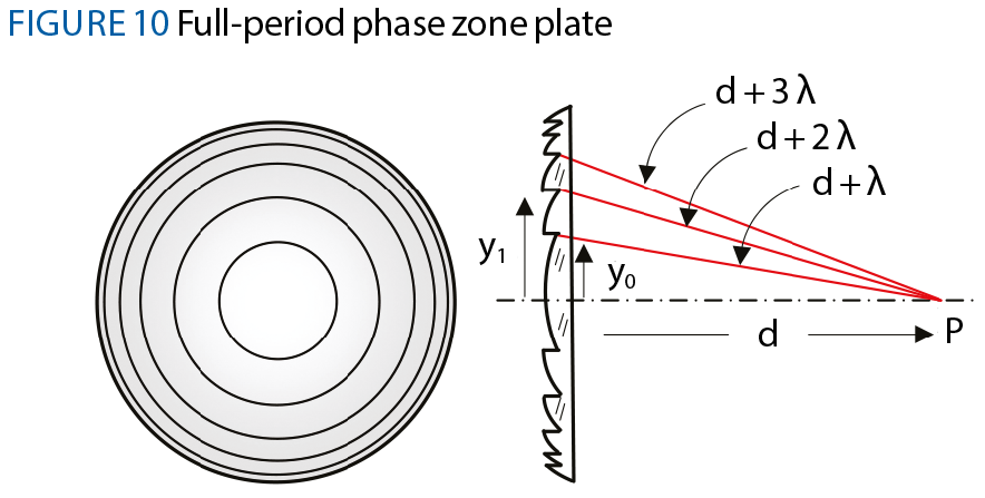
It can be seen from figure 10 that the radius of the central
circular zone, y0, is given by
y02 = (d + λ)2 - d2 = 2d λ
ignoring the term, λ2, which is very small. Thus the area of the central zone which contributes towards the light arriving at P is
2 π d λ.
The radius of the next zone, y1, is given by
y12 = (d + 2λ)2 - d2 = 2x2d λ
and the area of this whole zone is 2x2πd λ.
The area of the first annular zone around the central zone is thus 2πdλ, so this annular zone contributes the same amount of light at P as the central zone.
If the full-period phase zone plate has a series of m annular apertures, the radius of the mth ring will be
m x 2 d λ
and the area between this ring and the preceding one will, again, be 2πdλ.
Thus, each zone adds the same amount of light at P, which, therefore, all arrive in phase and sum constructively. This diffractive element or kinoform, behaves just like a plus lens focusing light at P (figure 10). It can be seen in figure 11 that there is a difference in the optical path length of the light as it passes through each successive zone of the kinoform similar to the difference when light passes through a converging lens.

Since the diffractive element focuses incoming light at the point P, this point must be the second principal focus of the full-period phase zone plate, F'. Using the same principle as shown in figure 10, but applying it to the diffractive element shown in figure 11,

ym2 = (f ' + m λ)2 - f '2 = m x 2 f 'λ
and the design equation for such a plate becomes ym2 = 2mf 'λ.
When written in the form
m = ym2 / 2f 'λ
this expression provides the number of zones, m, for a given diameter, 2ym (figure 12).

The diameter of the central zone, 2y0, is seen in figure 10 to be y02 = 2 f ' λ.
The focal length of the kinoform can also be found from the design equation,
f ' = ym2 / 2mλ.
The details of a kinoform, which has a power +1.00 D and diameter 10mm are determined as follows. The value of λ = 555nm or 555x10-6mm has been chosen from the middle of the visible spectrum.
The number of zones required, m, is first found from
m = ym2 / 2f 'λ = 52 / (2x1000x555x10-6) = 22.5.
The diameter of the central aperture, 2y0, is found from
y0 = √(2 f 'λ) = √(2x1000x555x10-6) = 1.05mm,
so 2y0 = 2.11mm.
In order to provide the on-off state of the electro-active segment, the kinoform, is sandwiched between a nematic liquid crystal such as BL037 whose refractive indices are, nE = 1.808, and nO = 1.526, to which is added the chiral doping solution ZLI-4571 (both substances manufactured by Merck & Co Inc USA), to form the cholesteric liquid crystal whose nAVG, (equal to (nO + nE)/2) is 1.667. This value matches that of several available
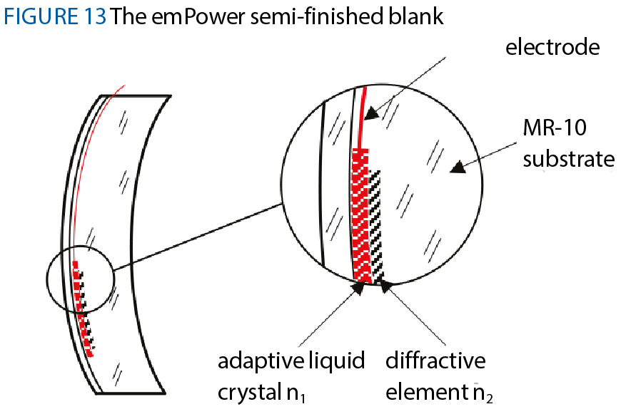
plastics materials (such as MR-10). The diffractive segment and liquid crystal are themselves cast just beneath the convex surface of a semi-finished blank with electrodes connecting the liquid crystal to the top of the semi-finished blank (figure 13). The electronics for the lens elements is assembled by Panasonic in Japan.
The semi-finished blank for the Pixel Optics emPower lens is illustrated in figure 13. The thin diffractive element is sandwiched between the substrate and the adaptive liquid crystal described above, and an invisible electrode which passes up through the lens to the frame rim which has further electrodes connecting each eye of the frame to the small battery contained in the tip of the right side of the frame. An important requirement of the frame design is to ensure the conductivity of the frame is not impaired by fluid such as wearer perspiration or water splashes which, for example, might occur in a rain shower.
When no current is passed to the nematic liquid crystal its refractive index, nAVG, is about 1.67, which is the same as that of the material from which the diffractive element and the surrounding substrate is made. As a result, the liquid crystal and kinoform have no optical effect. In this state the effect of the segment is cloaked.
When current is passed to the nematic liquid crystal, its refractive index changes instantly to 1.53 and the power of the segment is thus activated. When the current is switched off again, the refractive index of the nematic liquid crystal becomes 1.67 again, once again cloaking the segment element.
In the emPower frame design the current was switched on and off when the wearer tapped the side of the spectacle frame. One touch of the conductive material on the side switched the current on, and a second touch switched it off again. If the conductive material on the side was swiped forward it would activate a microgyroscope which switched off the current when the head was upright and switched it on to activate the segment when the head inclined to the reading position. The wearer could select either mode at will.
The power of the segment lens in the original design was +0.75 with the rest of the near addition being made up in the form of a progressive surface on the back of the lens. The segment was oval in shape with diameter 20 x 12mm and assuming λ = 550nm the number of zones required was
m = ym2 / 2f 'λ = 102 / (2x1333.3x555x10-6) = 68.2.
The diameter of the central zone, 2y0, is found from
y0 = √(2 f 'λ) = √(2x1333.3x550x10-6) = 1.21mm
so, 2y0 = 2.42mm
The depths of the concentric grooves of the transparent diffractive element are carefully controlled to provide the correct optical power. Figure 14 shows how the groove depth of the diffractive rings can be found.
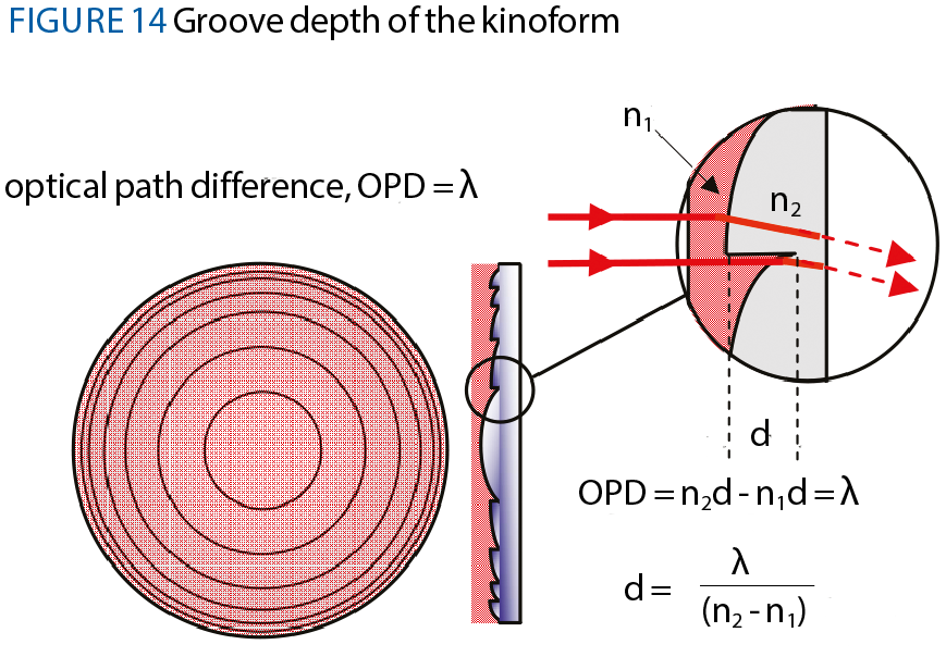
The kinoform, made from a material of refractive index, n2, is in contact with the nematic liquid crystal, whose refractive index is n1, and the optical path length of the upper of the two rays shown passing through the combination, differs from that of the lower ray by the depth of groove, d. The optical path length is given by the actual path length multiplied by the refractive index of the material so the optical path difference, OPD, is given by
n2d - n1d
Figure 14 shows that in order for the light from each zone of the full-period phase zone plate to arrive at P each path length must differ from its neighbour by one wave length, so
OPD = n2d - n1d = λ
Hence, the groove depth, d, is given by
d = λ / (n2 - n1).
For the emPower segment the groove depth is
550 / (1.67 - 1.53) = 3.93μm.
When the emPower adaptive spectacles were originally launched it was envisaged that the electro-active segments would be available in three additions, as shown below.
Full near Adds 1.25 to 2.00 - segment add +0.50 D
2.25 to 2.75 - segment add +0.75 D
3.00 to 3.50 - segment add +1.00 D
the remainder of the addition being provided by the progression worked on the back surface of the lens. Unfortunately, at the time of writing, the emPower product is no longer available. However, it is likely that the product will become available again at some future date.
Professor Mo Jalie is a visiting professor at Ulster University and author of the new edition of Principles of Ophthalmic Lenses.
References
- US Patent 7728949 (2010), Clarke R et al. Electro-Active Lens. Assigned to Pixel Optics, Roanoke, VA.
- US Patent 6491391 (2000), Blum RD et al. System, apparatus and method for reducing birefringence.
- US Patent 7731358 (2010), Blum RD et al. System, apparatus and method for correcting vision using an electro-active lens.