Spectacle and Ocular refraction; effective power
The spectacle refraction or prescription should, for powers arithmetically greater than 5.00 D, have a note of the vertex distance, as measured to the patient’s cornea.1 The effective power of this prescription, when measured at the corneal vertex is known as the ocular refraction.
Figure 1 shows a myopic eye corrected by a spectacle lens of power F'sp viewing a distant object. The image of this object is formed by the lens at F' which is at the eye’s far point MR at a distance ƒ'sp from the back vertex at S. For the eye, the object distance, k, is given by the distance:
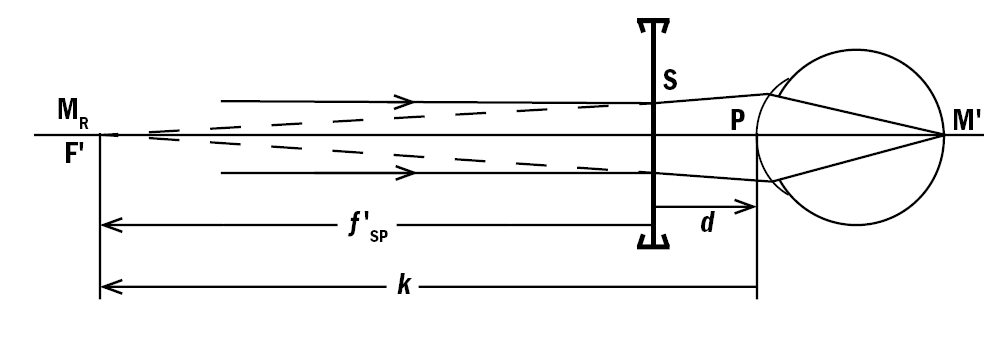
Figure 1: Spectacle and ocular refraction for a myopic eye
k = PF' = PS + SF' = –d+ƒ'sp Equation 1
And where ƒ'sp = SF' = 1/F'sp (m) = 1000/F'sp (mm)
Apart from using either vertex distance tables or a computer program to calculate k and then its reciprocal, K, the simplest way is to use the step-along method. For example, taking a spectacle refraction of -7.00 DS at a vertex distance of 13mm, the ocular refraction, K, is given by:
Alternatively, an equation linking the two may be obtained by taking the reciprocal of each side of equation 1 giving:
K = 1/(f'sp-d) = F'sp/(1-dF'sp) Equation 2
(Note – an italic letter K is used to denote the ocular refraction, an upright letter K for the keratometry readings.)
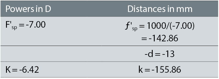
Figure 2 shows the ocular refraction as a function of the spectacle prescription for this 13mm vertex distance, while figure 3 shows the difference: {ocular refraction – spectacle refraction}. It should be noted that the difference is always positive, and increases rapidly with the amount of ametropia. This can be shown mathematically by expanding the denominator in Equation 2:
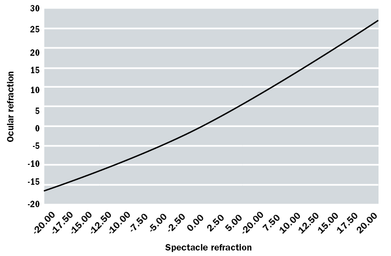 Figure 2: Graphical comparison of ocular refraction as a function of the spectacle refraction
K ≈ F'sp (1+(dFsp)+......) Equation 3
≈ F'sp + d(F'sp)2 + .....
Higher order terms involve d2, which, when expressed in metres, may be neglected. For low powers, there is a negligible difference – hence the statement in the British Standard cited above.1
When there is significant astigmatism, then the calculation must be done in both meridians since the cylindrical power also alters. Suppose the prescription had been -7.00 DS/-2.00 DC, again at 13mm. Proceeding as in the example above gives the ocular refraction in the -9.00 D meridian as -8.06 D, so the ocular refraction when expressed in sphero-cylinder form is -6.42 DS/-1.64 DC.
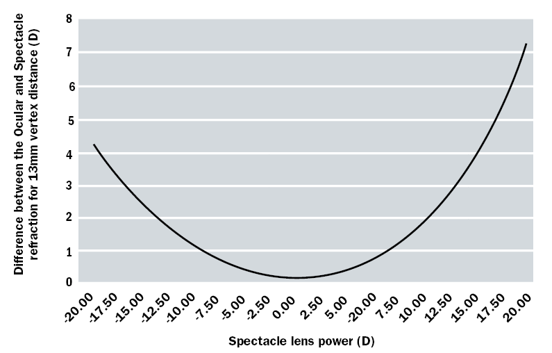 Figure 3: Difference between the ocular and spectacle refractions for a vertex distance of 13mm refraction
Soft lens powers to be ordered
For the young, pre-presbyopic patient where no compromise is needed between distance and near vision, one would expect the soft lens power required to correct the patient’s refractive error to be the ocular refraction. It is assumed that soft lenses drape on the cornea with no aqueous tears and hence no tear or liquid lens underneath. If there is only a low amount of astigmatism and the ocular refraction is expressed in negative cylinder form, the practitioner may decide for the first trial to correct either just the spherical element or the mean spherical equivalent (ie sphere + ½ cylindrical power). Thus, for the -7.00 DS myopic eye, an initial lens would be -6.50 DS. This may, however, prove to be slightly in error for three reasons.
The powers of some manufacturer’s lenses have been shown by Young et al,2 Belda-Salmerón et al 3 and Wagner et al 4 to differ from the nominal powers and certainly from other manufacturer’s lenses of the same nominal power.
Secondly, contact lenses have much steeper curvature than spectacle lenses, potentially giving spherical aberration. A soft lens on the eye will have a back optic radius matching that of the cornea, but even in the blister pack will have a radius generally between 8.5mm and 9.0mm. Even RGP lenses where there are no difficulties in maintaining hydration and regularity of shape, focimeter measurement is less precise than for a spectacle lens. The diameter and height of the contact lens support are reduced in comparison to those for spectacle measurement – in the range 4.0mm to 5.0mm.5,6
Although the difference in dimensions is primarily to put the back vertex of the contact lens in the same plane as that of a spectacle lens, the smaller aperture compared with the usual 5mm to 8mm for spectacle lens work will reduce the spherical aberration.7 In addition to a definition for paraxial back vertex power, the latest edition of ISO 18369-1 has the term: label back vertex power, F'L, which is defined as the ‘reciprocal of the back vertex focal length over the optic zone in air, expressed in dioptres’ with notes confirming that this is the optimal focus over the optic zone because of the influence of spherical aberration.8 Campbell tabulated the calculated mean power and the paraxial power of soft lenses, which suggests, as expected, that the mean power and hence the labelled power in many cases will be arithmetically slightly higher than the paraxial power.9
Thirdly, the average young eye with relaxed accommodation shows a small amount of positive spherical aberration, ie the rays passing through the periphery of the pupil come to a focus more anteriorly than the central or paraxial rays.10,11 Placing a contact lens on the eye may alter its spherical aberration. It has been argued that since the thickness profile of the lens from centre to periphery does not change when draping on the eye, the front surface of the lens will adopt the aspheric curve of the cornea and hence not alter the spherical aberration.12 Conversely, theoretical calculations by Cox,13 suggests that the aberration will alter. Many manufacturers make lenses with aspheric surfaces, but their literature may not make it clear whether the purpose is to not increase the spherical aberration when placed on the eye or additionally to correct the average eye’s spherical aberration. Because of the variation in spherical aberration between eyes, this may be advantageous for some wearers and disadvantageous for others.
Experiments by Koh et al 14 compared the spherical aberration through an aspheric design and a normal spherical design soft lenses – the aspheric design reduced the mean aberration to near zero irrespective of lens power, whereas the -7.00 DS spherical lens over-corrected the aberration, the -5.00 DS lens reduced it to zero and lenses of power between 3.00 and +3.00 DS all increased the SA.
Measurements by Lindskoog Pettersson et al 15 showed very little difference visually between the aspherical and spherical types of lens. The eye naturally reduces spherical aberration when accommodating, so perhaps lenses designed to reduce spherical aberration for distance vision may not be superior for near vision.
Population studies show that of the higher order aberrations represented by the Zernike polynomials, only the mean spherical aberration has a significant non-zero amount. There is therefore no point in trying to correct the other aberrations in a mass-manufactured product. If lenses were made for individual eyes, many of the aberrations are asymmetrical meaning that the orientation of the lens would have to be stabilised in a similar manner to lenses for astigmatism.
Soft lenses and astigmatism
Because a soft lens will drape on the cornea, any physiological amount of corneal astigmatism will be transferred to the front surface of the contact lens. Hence the cylindrical component of the ocular refraction should remain unaltered, whether or not the cornea is spherical or toroidal.
Thus a patient with an ocular refraction of -3.00 DS/-1.00 DC x 160 would be expected to show the -1.00 DC x 160 in an over-refraction through a soft spherical-powered contact lens. From this point of view, keratometry (or simulated keratometry with a corneal topographer) is not needed in soft lens fitting.
The study of Ministry of Health data in 1962 (cited in Rabbetts16) showed that around 66.6% of eyes had no or up to 0.50 D of astigmatism, 17.7% 0.75 to 1.00 D, and 15.7% over this. The data from the USA showed a greater proportion of nearly 26% having astigmatic prescriptions over 1.00 D.16
Soft toric lens misalignment
If a cylindrical lens intended to correct a patient's astigmatic error rotates off-axis, a new cylindrical error is induced at approximately 45° to the original axis, spoiling the vision. Campbell17 showed that the induced cylindrical error ΔC produced by similar cylindrical powers inclined at an angle Δα degrees is:
ΔC = 0.035 x (mean cylinder power) x Δα
Since it is accepted that a practitioner’s ability to verify whether a diagnostic contact lens’s power and axis relative to its engraving or other marking is poor (indeed, ISO 18369 3 gives reproducibility results only for wet cell measurement of power for toric lenses, whereas focimeter results for spherical powered lenses are stated), the practitioner must accept that the lens has been manufactured correctly. Hence if the lens has rotated so that its engraving or marking (whether intended to lie vertically or horizontally) is no longer in the intended position, a new lens should be tried with its cylinder axis orientated in relation to the rotated position of the lens rather than the horizontal. In figure 4, the lens has rotated 10° clockwise, so for a lens with a fiducial mark, M, that should be at six o’clock, the mark has rotated to the left. If the cylinder axis in the ocular refraction is at 160, then the angle between the vertical (90 down) and 160 is 70°, shown dashed in the figure. The next lens to be tried needs to have its axis, when on the eye, at 160, but this is now measured relative to the fiducial mark, not the vertical, ie the larger angle shown solid.
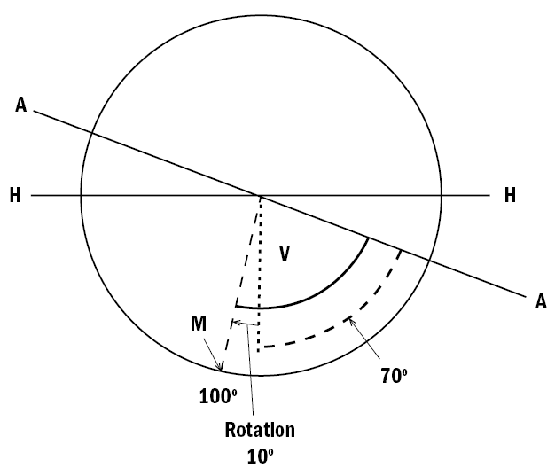 Figure 4: Illustration of a mis-aligned soft toric lens. HH: horizontal; AA: wanted cylinder axis; M: fiducial mark, rotated 10° to the left; dotted arc – angle between the vertical V and the cylinder axis; solid arc: angle between contact lens reference mark and the wanted cylinder axis
This gives rise to the LARS rule – if the six o’clock position has rotated to the Left, Add the angular error to the cylinder axis of the next lens to be tried. Conversely rotation to the Right requires the angular error to be Subtracted.
Keratometry readings and corneal astigmatism
Although the refractive index of the cornea is often taken to be 1.376, the back surface of the cornea cancels about 1/10th of the refractive power of the front surface. The tears film can be ignored on the non-lens wearing eye since it is uniformly thin and hence essentially of plano power, at least mid-way between blinks. Hence keratometers and corneal topographers are usually calibrated for a notional keratometer refractive index of 1.3375, although values of 1.332 and 1.336 were used by some manufacturers. This value is very close to the value for aqueous of 1.336 that is usually taken for the simple reduced eye, and of tears and hence the liquid lens trapped between rigid lenses and the cornea.
Using the standard equation for surface power and the notional index, the corneal power, Fc, is given by:
Fc = (nc-1)/(rc(m) = (1/3375-1)/(rc(m) = 337.5/(rc(mm))
Figure 5 shows the corneal power as a function of radius, while figure 6 shows the corneal cylindrical power for a 0.2mm difference in radius, again as a function of radius, eg for a radius of 8.0mm, the result is for the power at 7.9mm less that at 8.1mm. Although this varies with radius, the value at 8.2mm that a 0.2mm difference in radii is equivalent to 1.00 D makes an excellent and memorable rule. Having a decimal value on only one side of the equation makes one less likely to remember it incorrectly than the similar rule that 0.05mm difference in radius is equivalent to 0.25 D. Hence a cornea with radii or K-readings (keratometric or simulated keratometric with a topographer) of 7.80 mm along 175 by 7.60 along 85 has about 1 D of astigmatism. The near vertical meridian is the steeper, of ‘with the rule’ type, and the expected ocular refractive error would include -1.00 DC x 175. In practice, the crystalline lens frequently has about -0.50 DC x 90, so a more likely error would be -0.50 axis near horizontal.
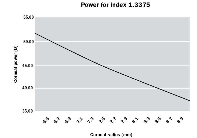
Figure 5: Corneal power for a notional index of 1.3375 as a function of corneal radius. (Note 7.5 mm gives exactly +45 D.)
Remembering that the power of a cylindrical lens is at right angles to the axis, one should not use the term axis in relation to K-readings, ie in the example above, the flat meridian may be described as being along or at 175, but not at axis 175.
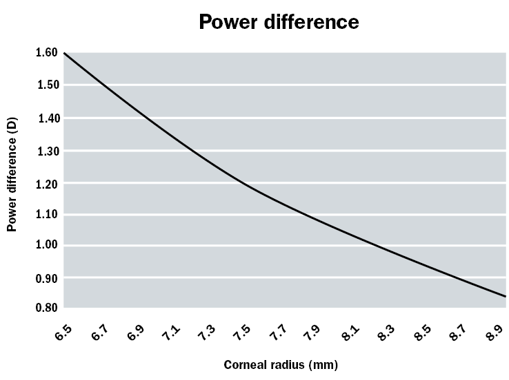 Figure 6: Difference in corneal powers for a radius difference of 0.2mm
This notional refractive index or 1.3375 is conveniently very close to the refractive index of tears, often taken to be 1.336. Hence a spherical (or aspheric) rigid contact lens of, say, radius 7.75mm will trap a liquid (or tear) lens with a spherical front surface and a toroidal back surface that will neutralise the corneal astigmatism. It is simplest to consider the back surface of the contact lens to be separated from the front surface of the liquid lens by an infinitely thin air boundary, and with another air boundary separating the back surface of the liquid lens and the front of the cornea.
Figure 7 shows, in exaggerated form, the cross section of the liquid lens in the 175° and 85° meridians. In the 175° meridian, there is a plus powered lens with a difference in radii of 0.05 mm, or ¼ of the value in the 0.2 mm ≈ 1.00 D rule, thus indicating a lens of power +0.25 D. In the 85° meridian, there is a negative powered lens with a radius difference of 0.15 mm, which is ¾ of the rule value. Hence the power in this meridian is -0.75 D, and the cylindrical power provided is -0.75 -(+0.25) D = -1.00 D. The minus power is along the 85° meridian, so that the cylinder axis is 175, exactly what is needed to neutralise the corneal astigmatism.
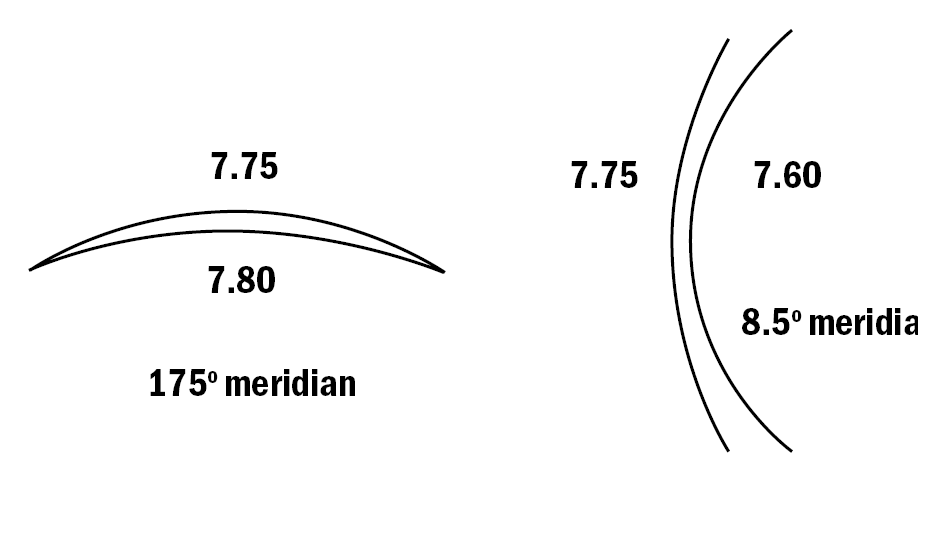 Figure 7: The liquid lens in the 175° and 85° meridians. When combined, this neutralises the corneal astigmatism
Hence, provided the rigid contact lens does not warp or tend to mould itself to the corneal curvature, a spherical (or aspheric but not toroidal) back-surfaced lens will correct the corneal astigmatism. Any astigmatism remaining uncorrected is termed ‘residual astigmatism’. Provided the mechanical fit of a spherical lens on a toroidal cornea is acceptable, a rigid lens will correct significant amounts of corneal astigmatism without requiring complicated geometry. The optics of toric contact lenses will be discussed later in this article. For the same reason, rigid lenses are used in fitting distorted or scarred corneas such as in keratoconus.
This discussion enables a practitioner to estimate the power to be ordered of a rigid contact lens. Suppose the patient's spectacle refraction is -4.00 DS/-1.50 DC x 10 at 15mm and the K-readings are 8.00 along 5 x 7.65 along 95. The orientation of the K-readings is close enough to the cylinder axis, and the difference can be ignored. Using the process at the beginning of this article, the ocular refraction is -3.77/-1.31 x 10. The difference in K-readings suggests a -1.75 x 5 corneal cylindrical refraction, which is compatible with the ocular refraction. Suppose a contact lens of BOZR of 7.90 is chosen as the first diagnostic lens. Then the expected power can be calculated solely on the basis of the spherical component of the ocular refraction when expressed in minus cylinder form, the flatter of the two corneal radii and the BOZR of the lens. In this case, the lens is 0.1mm steeper than the corneal radius of 8.00, thus trapping a positive-powered liquid lens of +0.50 D. The contact lens must provide both the -3.77 D of the ocular refraction and an extra -0.50 D to overcome the induced power in the liquid lens, ie a -4.25 D lens when rounded to the nearest 0.25 D step. If the trial diagnostic lens had a power of -3.00 DS, then an over-refraction of -1.25 D would be expected. If a significantly different value is found, then the data should be rechecked: was the lens of the correct radius, has the patient gone into accommodative spasm, does the fluorescein fit match the difference in radii?
Change in BOZR and the compensatory change in BVP
A similar process should be used to calculate the BVP to be ordered if the BOZR of a rigid lens is altered. The first step is to imagine a liquid lens formed between the new and original BOZR, as shown in very exaggerated form in figure 8, again with an air boundary on either side. Suppose that in a contact lens fitting, the patient had an over-refraction of -1.25 DS when wearing a trial lens of BVP -3.00 DS, but it is decided to order a lens 0.1mm steeper. With the original lens, as shown in the upper part of figure 8, the power required at point V is therefore -4.25 DS. In the lower diagram, this same power is needed at point V, behind the new imaginary lens but in front of any original liquid lens. The latter can therefore be ignored since it is common to both situations.
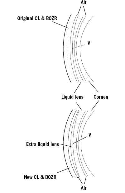 Figure 8: Compensation of BVP for a change in BOZR. Upper: the original lens on the eye, Lower: the new lens on the eye trapping an extra liquid lens
The imaginary liquid lens has its front surface 0.1mm steeper in radius than the back surface. This lens therefore provides a positive power of value (0.1/0.2) ×1.00 = +0.50 DS. Hence the lens to be ordered must have its power increased by -0.50 DS to compensate so that the BVP should be -4.75 DS. Hence the rule: If the BOZR is steepened by 0.20mm, the power must be made more negative by -1.00 DS. Obviously the practitioner is far more likely to order a lens with a change in BOZR of only 0.05 or 0.10mm, but again keeping the decimal value on only one side of the ‘equation’ makes remembering easier.
Lens movement and pupil size; change in BOZD and BOZR
Soft lenses have relatively large optic zones, often 8mm or more in diameter and are relatively stable in position on the eye so that the pupil is well aligned with the zone. Corneal lenses, however, both move significantly on the eye and have smaller optic zones so that if the lens high rides being held by the upper lid or drops after the blink to rest on the lower lid, there is the possibility that the whole pupil area is not covered by the optic zone but is partly covered by the peripheral zones. These will have a prismatic effect so that light from the side or above/below will be refracted into the eye along the same direction as light from the object of regard. This gives rise to flare, which will fluctuate with lens movement on blinking or eye rotation. Thus if a first trial is made with a lens with a BOZD of, say, 7.00mm, the practitioner may decide to order a larger lens with a BOZD of 7.50mm. It used to be accepted that an increase in BOZD of 0.5mm required a compensating increase in BOZR of 0.05mm to give the same clinical fit. Since the radius has been flattened, a compensating change in lens power of +0.25 DS should be made. Modelling spherical surfaces on a typical aspheric cornea with p-value of 0.7 does not suggest that such a large radius compensation need be made. With lenses with aspheric back surfaces, the manufacturer’s literature should be consulted for the need for any compensatory changes in radius should the overall size, and hence BOZD, be altered.
The optics of rigid back surface toric lens fitting
This discussion is applicable only if the axis of the corneal astigmatism is the same as or close to that of the cylinder axis in the spectacle or ocular refraction. If the spectacle cylinder is in minus cylinder form, the axis should match the orientation of the flatter meridian of the K-readings. A mis-match between the two has traditionally implied significant astigmatism in the crystalline lens at an axis oblique to the corneal astigmatism. Another possibility might be a corneal apex that is decentred more than usual, the corneal geometry giving unrepresentative K-readings.
Although the lens manufacturer will usually do the calculations if provided with all the data, the practitioner should have an understanding of the arithmetic. Taking an example, a patient’s ocular refraction is -2.50/-3.50 x 180 and the K-readings are 8.00 along 180 x 7.40 along 90. Initially, a spherical lens of BOZR 8.00mm is tried. The lens aligns along the flat meridian, hence giving a zero power liquid lens, but because of the large radius differences in the vertical meridian, exact calculation of liquid lens power is needed rather than use the approximate rule:
Power of front surface of liquid lens = (1000*(1.336-1))/8.0 = 336/8.0 = +42.00D
Power of back surface of liquid lens= (1000*(1-1.336))/7.4 = -336/7.40 = -45.41D
Hence power of liquid lens in the vertical = +42.00 + (-45.41) = -3.41 D, thus correcting all but 0.09 D of the patient’s ocular cylindrical power.
This lens is unlikely to fit well, so suppose that a toric lens of refractive index 1.435 with back surface radii of 8.00 x 7.50 (ie slightly less toroidal than the cornea) is now chosen. The calculations in table 1 assume imaginary air boundaries between the contact lens and tears and tears and cornea.
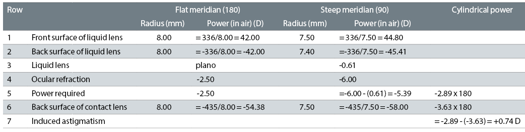 Table 1: Example of a toric lens calculation
It is simplest to work in the two meridians, and consider the cylindrical powers only towards the end of the calculation. Again, there is a plano power liquid lens in the horizontal meridian, but in the vertical meridian, the power is now only -0.61 D, as shown in row 3 of table 1. Hence, allowing for the liquid lens power, the power required of the contact lens, row 5, is -2.50 in the horizontal meridian x -5.39 D in the vertical meridian, or -2.50 / -2.89 x 180.
We must now take into account the cylindrical power of the back surface of the contact lens; row 6 shows that this is -3.63 D x 180, which over-corrects the patient’s ocular astigmatism by 0.74 D. This over-correction is known as the ‘induced astigmatism’, ie the astigmatism that is caused by the cylindrical power of the back surface of the rigid toric lens exceeding the corneal and liquid lens astigmatism. If the back surface of the contact lens had exactly matched the corneal radii, there would have been a plano liquid lens in both meridians, so that the cylindrical power required would have increased by 0.61 D to -3.50 D, but the cylindrical power of the back surface of the contact lens would have increased more by -0.78 to -58.78, increasing the induced astigmatism to 0.91D. Even reducing the toricity of the contact lens to 2/3 of that of the cornea still leaves 0.50 D of induced astigmatism. Fortunately, the refractive index of modern high Dk RGP materials is lower than that of PMMA or early low Dk materials, so that the induced astigmatism is less.
To correct the patient’s cylindrical error with a back surface toric lens frequently requires the manufacturer to use a toroidal front surface to eliminate the induced astigmatism, and simultaneously any residual astigmatism from the crystalline lens. These lenses are difficult to manufacture since it is difficult to keep the meridians of the front and back surface parallel to each other. Some bitoric lenses were designed to behave as a spherical powered lens on the eye, the cylindrical power on the front surface exactly cancelling out the induced astigmatism produced by the toroidal back surface.18,19
Summary
Knowledge of ocular versus spectacle refraction is important for all contact lens fitting. Spherical soft lenses should make no difference to any ocular astigmatism, while misalignment of toric lenses is best dealt with by simply making an allowance for the angle of rotation. Rigid lens fitting needs an understanding of the effects of the liquid lens on the contact lens prescription, whether in correcting corneal astigmatism, or in increasing or reducing the necessary spherical element of the refraction.
Ronald Rabbetts is a retired optometrist and chairman of BSI spectacles (frames and lenses) committee and member of the sunglasses committee.
Part 2 in this series will cover accommodation and magnification effects of contact lens wear.
References
- BS 2738:2004 + A1:2008: Spectacle lenses – Part 3: Specification for the presentation of prescriptions and prescription orders for ophthalmic lenses. British Standards Institution, 387 Chiswick High Road, London W4 4AL
- Young G, Lewis Y, Coleman S and Hunt C. (1999) Process capability measurement of frequent replacement spherical soft contact lenses. Contact Lens Anterior Eye, 22 (4), 127-135
- Belda-Salmerón L, Madrid-Costa D, Ferrer-Blasco T, García-Lázaro S, and Montés-Micó R. (2013) In vitro power profiles of daily disposable contact lenses. Contact Lens Anterior Eye, 36, 247-252
- Wagner S, Conrad F, Bakaraju RC, Fedtke C, Ehrman K and Holden BA. (2015) Power profiles of single vision and multifocal soft contact lenses. Contact Lens Anterior Eye, 38, 23-14
- ISO 8598-1:2014 Optics and optical instruments – Focimeters – Part 1: General purpose instruments, International Standards Organisation, Geneva (available as BS EN ISO 8598-1 through British Standards, 387 Chiswick High Road, London W4 4AL)
- ISO 18369-3: 2017 Ophthalmic optics – Contact lenses – Part 3: Measurement methods, International Standards Organization, Geneva (will be available as BS EN ISO 18369-3-1 through British Standards, 387 Chiswick High Road, London W4 4AL)
- Freeman MH and Hull CC. (2003) Optics 11th Ed, Oxford, Butterworth-Heinemann, 240-248
- ISO 18369-1: 2017 Ophthalmic optics – Contact lenses – Part 1: Vocabulary, classification system and recommendations for labelling specifications, International Standards Organization, Geneva (will be available as BS EN ISO 18369-1 through British Standards, 387 Chiswick High Road, London W4 4AL)
- Campbell CE, (2009) Spherical Aberration of a Hydrogel Contact Lens when Measured in a Wet Cell, Optometry and vision Science, 86(7), 900-903
- Porter J, Guirao A, Cox IG and Williams DR. (2001) Monochromatic aberrations of the human eye in a large population. Journal of the Opt Soc Am A Image Sci vix, 18(8), 1793-1803
- Kingston AA and Cox IG. (2013) Population spherical aberration: associations with ametropia, age, corneal curvature and image quality. Clinical Ophthalmology, 7, 933-938
- Dietze HH and Cox MJ. (2003) On- and off-eye spherical aberration of soft contact lenses and consequent changes of effective lens power. Optom Vis Sci, 80, 126-134
- Cox I. (1990) Theoretical calculations of the longitudinal spherical aberration of rigid and soft contact lenses. Optom. Vis Sci, 67, 277–282
- Koh S, Maeda N, Hamada T and Nishida K. (2014) Efficacy of spherical aberration correction based on contact lens power. Contact Lens Anterior Eye, 37, 273-277
- Lindskoog Pettersson A et al. Spherical aberration in relation to visual performance in contact lens wear. Contact Lens and Anterior Eye. 2011 Feb;34(1):12-16.
- Rabbetts, RB (Ed). Clinical Visual Optics, 4th Ed, Butterworth-Heinemann, Oxford
- Campbell, C (1999) A method to analyze cylinder axis error. Opt Vis Sci, 76:254-255
- Douthwaite, W. A. (1988) Technical note: compensated toric rigid contact lenses. J Br Contact Lens Assoc, 11(2), 35–38
- Douthwaite WA. (2006) Contact Lens Optics and Lens Design, 3rd edn. Oxford: Butterworth-Heinemann