At a recent CET workshop, more than 100 dispensing opticians and optometrists were asked to measure the PD of a model child’s head. Anonymous answers were written on a slip of paper and placed in a ballot box.
The results showed that half of all present could not take a PD. Despite the ‘patient’ being the most cooperative and compliant child ever known, the organisers were astounded to discover that the measurements taken varied by a staggering 11mm.
Doubtless, most delegates measured PD daily and would in advance probably have considered a large group of registered opticians to be competent at this most fundamental of tasks. Yet the figures spoke for themselves and indicated at first glance that a patient may be no worse off buying their spectacles from an online retailer that uses average measurements.
The inspiration for this informal experiment was the research of Walsh and Pearce who asked 54 opticians to measure the PD of one patient.1 They presented similar results as can be seen from the graph (figure 1). It shows an average measurement of 68mm and that 50% of opticians measured the patient to be between 67mm and 68.5mm. It follows therefore that many of the remaining measurements are likely to result in lens centration, especially for progressive lenses, that is outside British Standard tolerances.
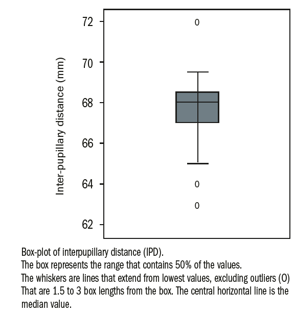
Figure 1: 54 opticians measured the PD of one patient.1
This article explores why such errors occur and explains how they can be avoided.
Definitions
There are several landmarks or reference points used in the measurement of PD, each of which brings its own issues in terms of accuracy, error and suitability as a measurement for certain kinds of lenses.
PD measurement landmarks
These are illustrated in figure 2.
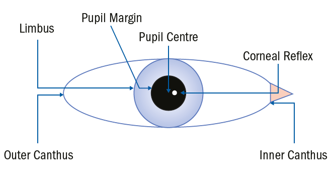
Figure 2: PD measurement landmarks
Whatever method is employed the measurement itself is defined in BS EN ISO 13666:2012 section 5 as follows: the distance between the centres of the pupils when the eyes are fixating an object at an infinite distance in the straight-ahead position (see figure 3).
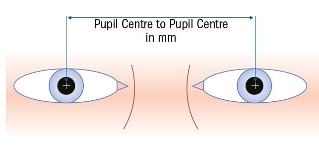
Figure 3: Interpupillary distance (PD)
Despite pupil centre to pupil centre being the defined measurement, and it being the only appropriate method other than corneal reflex pupillometry when measuring for the centration of progressive power lenses, there are a variety of other methods of measuring binocular PD with similar levels of accuracy. These include:
- PD – outer pupil margin to inner pupil margin (figure 4). This is a difficult measurement to take on dark irises and inaccurate when pupils are different sizes (anisocoria) or shapes (eg iris coloboma)
- PD – outer limbus to inner limbus (figure 5).It may be difficult to gauge the centre (or edge) of the pupil when the iris is very dark so measuring outer limbus to inner limbus may be easier but is inaccurate when pupils are not located centrally and is inappropriate when accurate mono-PDs are required.
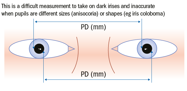
Figure 4: Outer pupil margin to inner pupil margin
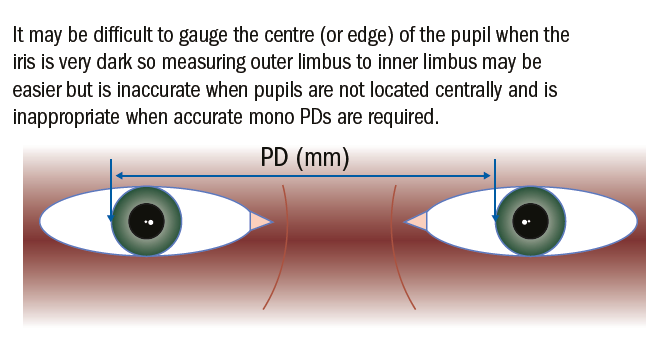
Figure 5: Outer limbus to inner limbus
All dispensing opticians, optometrists and optical dispensers need to be able to take monocular PDs accurately to pupil centres if they are dispensing aspheric or progressive lenses of any power, or high-powered lenses of any type. Accordingly, it is recommended that practitioners form the habit of measuring all patients from pupil centre to pupil centre and only utilise the other methods for checking their total binocular measurement.
The carpenters’ adage, ‘measure twice, cut once’ is sound advice and may have prevented the outlying measurements mentioned in the experiments above. It should be normal practice, regardless of experience, to always double check measurements, and the more expensive the lenses or the more sensitive the patient, then the more carefully the measurements should be checked.
Measuring Distance PD
It is now common in practice to use desk top, stand mounted, or tablet computer-based systems for measuring PD (figure 6). Overall such computerised systems may be more accurate for most patients; however, there are limitations to their use and it is important that practitioners can still use a PD rule. Additionally, there are considerable advantages to using a pupillometer for a minority of patients and practitioners. Many practices that have disposed of their pupillometer on taking delivery of iPad-based systems have lived to regret it.
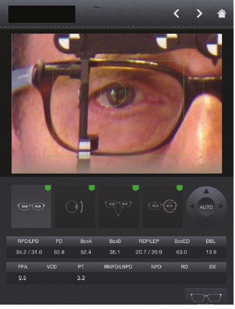
Figure 6: PD measurement using a tablet
Such systems depend on the practitioner taking a good quality image, and then centring a fitting cross over the pupil centre on screen. In the author’s experience presbyopic opticians in denial are no more accurate at aligning these crosses than they are at using a ruler. Tablet systems are also dependent on the tablet being held straight about the anterior-posterior (front to back), transverse (side to side) and vertical axes and failure to do so can result in error (borrowing nautical terms these errors are of tilt, pitch and yaw respectively). The most sophisticated systems that employ an additional PC based server connected to the tablet are able to utilise the gyroscope within the iPad and make complex calculations to compensate for these sources of error.
Alternatively having a fixed system that is mounted on the dispensing desk or a height adjustable stand is a sure way of eliminating these kinds of errors.
Measuring PD with a PD Rule (figures 7 to 9)
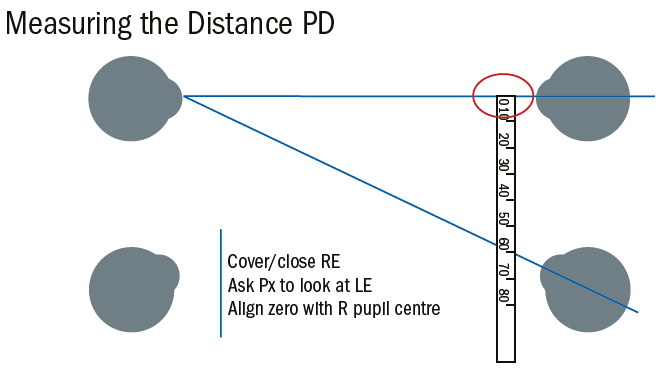
Figure 7: The optician closes their right eye and asks the patient to look at their left eye and aligns the end of the rule to the patient’s right pupil centre. Note that the optician’s covered eye and the patient’s left eye are each converging because of the close working distance.
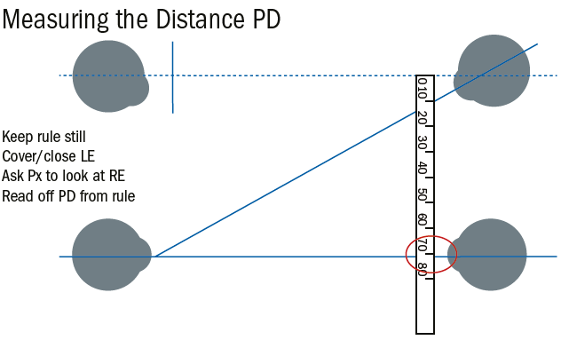
Figure 8: Next the optician closes their left eye and asks the patient to look at their (now open) right eye taking care that the patient, the ruler and the optician do not move. The PD can then be read off the rule at the left pupil centre
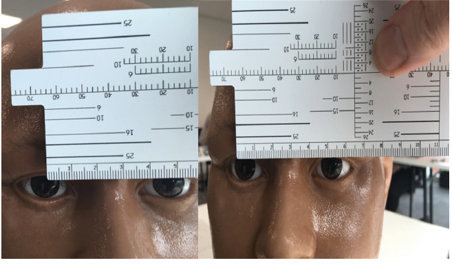
Figure 9: The images attempt to simulate the measurement of PD with a frame rule though obviously the model head is not capable of convergence or eye movement. Initially the phone camera is aligned exactly in front of the right eye and the rule set with zero at pupil centre. Note if the optician were to look across using only their left eye at this point even with this static model they would read off a greatly reduced PD (showing here at around 47mm) due to parallax error. When the optician uses their right eye to observe the patient’s left eye the PD can be read off as 52mm here simulated by moving the phone camera to be aligned in front of the patients left eye. Note the change in perspective and also that the end of the rule appears to have moved to the left even though it has remained still.
Student dispensing opticians and optometrists are required to be able to use a rule for the purposes of examinations and it is important to understand the common causes of error in optical centration even if other methods are used in practice. In preparation the optician should ensure they are sat squarely in front of the patient and adjust their seat to ensure their eyes are on the same level.
As the optician will be invading the personal space of the patient it is usual to obtain consent at this point. This need not be onerous or in writing. Having explained the need to measure between the pupil centres the patient should be warned of the need to rest the ruler against their brow and the possibility of the optician steadying their hand against the patient’s temple, at which point they should verbally agree.
The method above works well for most patients, and most practitioners; however, in certain circumstances it is not appropriate.
Patients with strabismus
Patients with a squint, or turn in the eye, are like to be measured inaccurately unless special procedures are adopted. A turn in the eye may be permanent as in heterotropia, or it may be that the patient can compensate for it either partly or in full once they are wearing their spectacles, this being especially true of patients with significant hypermetropia or hypermetropic astigmatism.
As such it is good practice to adopt the technique for strabismus on all children, and all long-sighted patients, and not only those with prescribed prism. Figure 10 shows the measurement of a patient with a left esotropia – that is when the patient is asked to look at an object straight ahead the right eye fixates the object whereas the left eye turns in. This will cause double vision and as a result the brain will ignore the image from the left eye (suppression). In a young child this will result in a failure of the nerves from the left eye to the brain to connect up properly and result in a lazy eye (amblyopia – dull vision). It is important therefore to measure the PD accurately so that the lenses, including any prescribed prism, are centred correctly and the double vision alleviated.
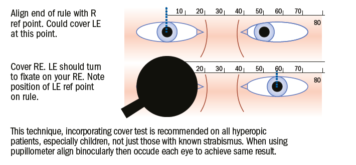
Figure 10: Measurement of PD in patient with strabismus – in this case left esotropia.
This technique in figure 10, incorporating a cover test, is recommended on all hypermetropic patients, especially children, not just those with strabismus. When using a pupillometer, align binocularly then occlude each eye to achieve the same result. In practice it is rare that a muscle imbalance is so obviously noticeable, and furthermore patients may exhibit an alternating squint. It is therefore recommended that each eye is occluded in turn, while the other is measured, on all occasions.
Monocular opticians, or those that are amblyopic, will require to use a different method, (such as the corneal reflex pupillometer or computer/camera-based system) and those that are unable to close one eye easily may prefer to. Alternatively, they can measure the near centration distance, which requires them to use only one eye, and calculate the distance PD from this measurement.
Due to the need for a close working distance at eye level measuring PD, and especially NCD, using a ruler can be quite a challenge for presbyopic opticians wearing general purpose progressive lenses. Many invest in a specific occupational solution for use at the dispensing desk such as enhanced readers. As a result, many find themselves offering and dispensing occupational lenses to their clients far more regularly than their non-presbyopic counterparts, presumably because there is no education like first-hand experience.
Monocular Interpupillary Distances
Mono PDs are essential when dispensing progressive power lenses (PPLs) so that each eye looks through the correct part of the lens when working at intermediate and reading distances. The corridor on progressive lenses can be as narrow as 2mm in some old designs (when the reading addition is high, and the prescription incorporates significant astigmatism) so even 1mm error can make all the difference. For this reason, according to BS EN ISO 21987:2009 5.5.2.2 the manufacturing tolerance for PPL monocular centration is only 1mm regardless of power. It is also important to take mono PDs on all high powered and aspheric lenses for the patient to experience optimum visual performance and where similar tolerances are in force.
Whatever method is employed, the measurement itself is defined in BS EN ISO 13666:2012 section 5.30 as follows and as shown in figure 11: Monocular pupillary distance is the distance between the centre of the pupil and the mid-line of the bridge of the nose or the spectacle frame when the eye is in the primary position (looking straight ahead at eye level)
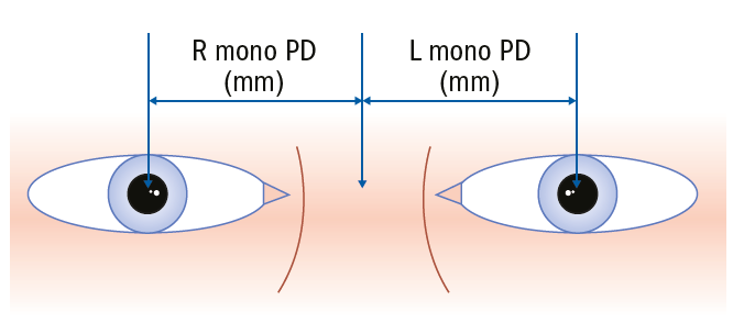
Figure 11: Monocular pupillary distance (mono PD)
It can be measured with a conventional rule, but there is scope for error in ensuring the centre of the bridge is consistently identified (figure 12).
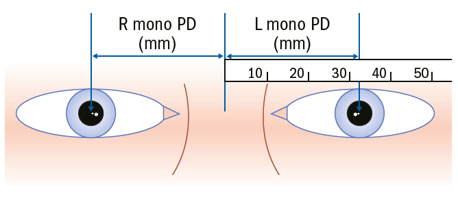
Figure 12 Measuring mono PD with a conventional rule.
It is best to use a mono PD rule which makes it easy to identify the centre of the bridge (figure 13).
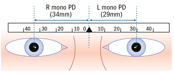
Figure 13: Use of a mono PD rule
Pupillometers
Until recently, the most common method of mono PD measurement was to use the corneal reflex pupillometer (figure 14). Unlike other methods this measures the distance between the visual axes, and not the pupil centres of the eyes. The visual axis of the eye is slightly nasal to the presumed optical axis because the optical centres of the various components of the optical system of the eye (anterior and posterior cornea surfaces, aqueous humour, anterior and posterior lens, vitreous humour) are not perfectly aligned. The visual axis is typically 0.5mm nasal of the pupil centre and is the more appropriate measurement to use.
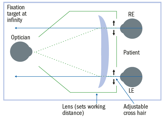
Figure 14: Pupillometer for distance PD measurement
Figure 14 shows the setup of a corneal reflex pupillometer for distance mono PD measurement and figure 15 for near. Note that the working distance is selected by turning a dial which moves a lens system inside the machine.
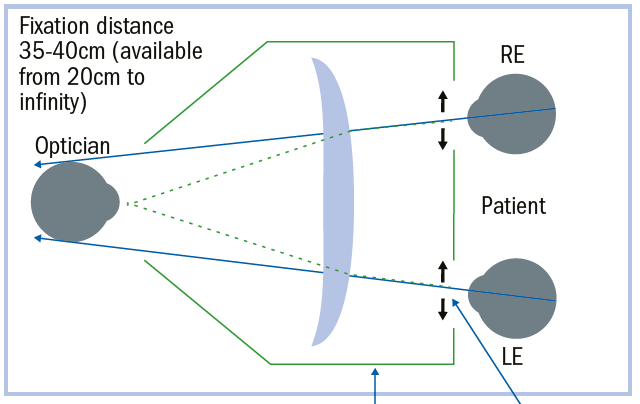
Figure 15: Pupillometer for near CD measurement
To use the pupillometer, the following steps should be followed:
- Select the appropriate working distance and move the cross hairs to their widest point
- Place the pupillometer on the bridge of the patient’s nose with the brow bar against their forehead
- Ask them to hold the pupillometer like a pair of binoculars and fixate the light/target inside
- Align the cross hairs binocularly with the corneal reflex of each eye, and check by occluding each eye in turn, that the eye doesn’t move when the other is covered. If it does realign the cross hairs read off the measurement and repeat for a new working distance as desired
Figure 16 shows a pair of Essilor Corneal Reflex Pupillometers, the left with cross hairs aligned for a PD of 48mm and the right for 77mm this being the range for this model. The right also shows a working distance of infinity. The working distance is obscured by reflection on the left; however, it can be selected for the range from 35cm to 200cm as well as far distance.
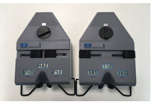 Figure 16: Essilor corneal reflex pupillometers
Figure 17 shows the top of the pupillometer on the left with the occluder set to cover the left eye. Note the light which indicates the device is switched on, which happens automatically – if it is left this way round the battery will flatten, whereas if left on the reverse (as when reading the measurements) it will switch off automatically after a couple of minutes. When transporting pupillometers the batteries should be removed.
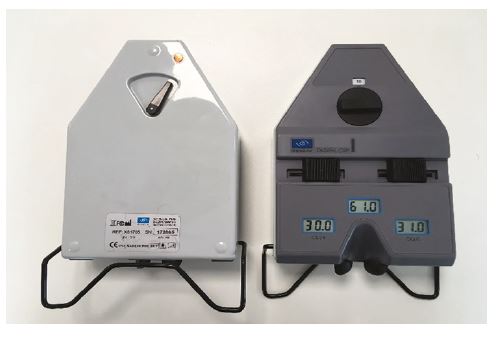
Figure 17: Occlusion of left eye in pupillometer
Figure 18 shows the view inside the pupillometer of a model baby’s head and the cross hairs across the pupil very nearly aligned to the corneal reflex.
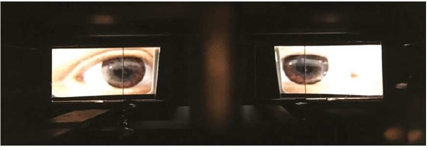
Figure 18: View through pupillometer
Calibration of pupillometers
It is good practice to always check pupillometer measurements by at least performing a binocular PD by another method and checking that they correspond to within 1mm. Additionally, by moving the cross-hair controls to their narrowest and widest points the figures given should always remain the same (in the case above, 48 and 77mm) if the pupillometer is still correctly calibrated. The device can also be checked by using a Norville calibration tool (figure 19), which is essentially a rule with a special bridge bump that can be used to check that measurements remain accurate.
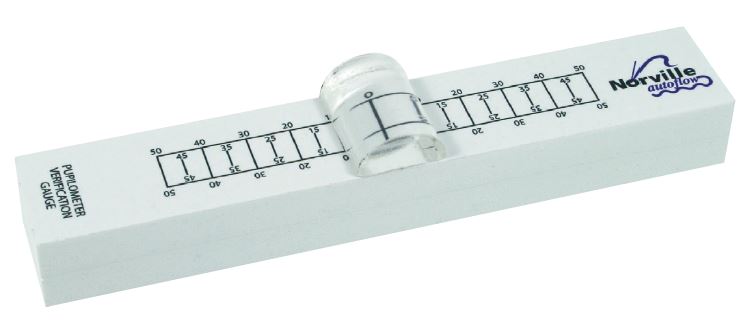
Figure 19: The Norville calibration tool
Errors in PD and mono PD measurements
It is recommended, especially for progressive power lenses, that the patient’s mono PD measurements (and heights which will be covered in another article) are marked on the dummy lenses after they have been determined and physically checked for alignment with the frame in place. This helps prevent error caused when the optician and patient do not sit face on and square to each other.
It is often necessary to observe the patient for a few minutes or longer, and ideally in a standing as well as a seated position to ensure accurate centration. Patients often alter their head position when being measured, leading to poor lens performance once they adopt their natural position later. Additionally, the patients chosen frame is highly likely to sit differently about the bridge of the nose than either a mono PD rule or a pupillometer, especially if the patient’s nose is asymmetrical. Tablet computer systems are also prone to these kinds of errors as they rely on the optician’s estimate of the centre of the bridge.
Facial asymmetry
It is useful to consider a patient with a broken nose whose mono PDs may show a reversal of asymmetry depending on the wearing position of the frame. This means that if the glasses slip down the nose the patient will have to turn their head upwards more than usual and to one side to see clearly.
Figure 20 shows how a broken nose can lead to different mono PDs depending on the position of the frame. The selection of a frame with adjustable nose pads is preferable in these circumstances as it allows some adjustment laterally which would not be available with fixed pad bridges, as well as offering the ability to raise or lower the frame too.
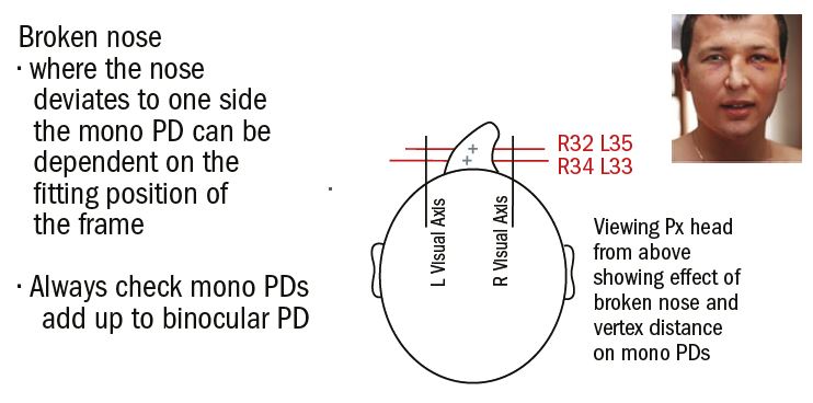
Figure 20: Mono PD problems; impact of facial asymmetry
The pen to lens technique
Another cause of error includes marking the pupil centre on the lens with the frame in situ (figure 21). Although this method can be a speedy one, there is a tendency for patients to recoil slightly as the pen approaches, often moving their head upwards and slightly to one side which can lead to inaccurate measurements. Better to add the markings after measuring through a different method and then check on the patient.
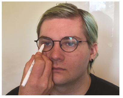
Figure 21: Spectacles in situ with hand drawn crosses in front of pupil centres
Look at my pen
It is common for opticians to ask the patient to look at their pen, a budgie stick or similar instead of their open eye pupil centre. They often hold the pen to the side of their eye instead of directly below it. Holding the pen an inch (25mm) temporally to each side will over-estimate the PD by 3mm and is a particular problem with young children who are most likely to be exposed to this technique as a means of attracting their attention and are already more likely to suffer error due to their small size relative to the optician.
Error due to variation in PD between optician and patient
Figure 22 shows the error (2d) inherent when the optician’s PD is considerably different to that of the patient. In this case a child, PD 48, is being measured by an optician with a PD of 72. It is assumed the rule is held in the notional spectacle plane 27mm in front of the centre of rotation the patient’s eye and 400mm from the optician. Using similar triangles;
d/27 = 12/427
so d = 0.76mm
the overall error is approximately 1.5mm. This is error is minimised by holding the ruler as close as possible to the patient and increasing the working distance to the maximum possible. For example, if these measurements were 20mm and 600mm respectively the error would be reduced to 0.8mm.
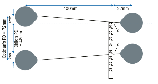
Figure 22: Error due to PD difference between patient and practitioner
Measuring Near Pupillary Distance
During near vision the eyes converge, moving closer together so that the distance between pupil centres is reduced. Because the distance between the pupils is measured in the plane of the spectacles and the visual axes converge towards the near vision fixation point, the near centration distance is less than the actual distance between the pupils.
Near Centration Distance
Near centration distance (NCD) can be measured as part of the process of measuring the PD (figure 23), as a separate measurement (figure 24) or it can be determined by calculation.
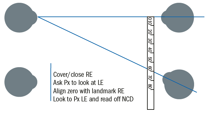
Figure 23: How to measure near CD during distance PD measurement.
Figure 24 shows the midline technique which must be used if mono NCD is to be measured accurately using a ruler. It is also the only accurate method for a monocular optician and from which accurate distance mono PDs can be calculated if other methods of measurement are not available.
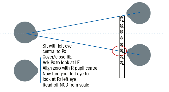
Figure 24: Midline technique for near CD measurement
Calculating NCD
The near centration distance can be calculated accurately providing we have the following information: distance PD; working distance; vertex distance of the spectacle lens; position of the centre of rotation of the eye (figure 25). In practice we assume that the distance from the centre of rotation to the spectacle plane is 27mm, and as such the NCD becomes a function of the PD and the working distance and can be calculated easily using similar triangles.
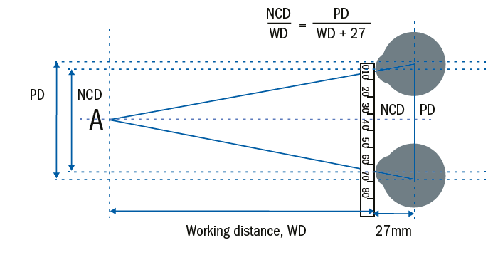
Figure 25: Calculating the NCD
If the NCD is 60mm and PD 70mm, as in figure 25. To calculate the working distance;
NCD(WD+27)=WD x PD
60WD+1,620 = 70WD
WD = 1620 / (70-60) = 162mm = 16.2cm
Clearly, this is an exaggerated example with such a close working distance that would rarely be practical outside of low vision dispensing where high adds resulting in close working distances and large insets are the norm. However, table 1 shows the calculated NCDs for a variety of PDs and working distances. It shows that for standard working distances and below average PDs the traditional reduction of 4mm is accurate, and for above average PD measurements a 5 mm difference is appropriate.
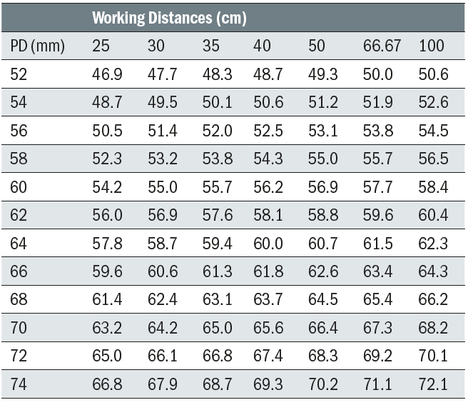
Table 1: Calculation of NCD given PD and Working Distance
Calculating NCD measurements (or ‘knocking off 4mm’) is frowned upon by many optical practitioners, yet it is often more accurate. Poor near vision on the part of the optician and an inability to position oneself at the appropriate working distance to measure NCD, often because of poor dispensing area design, all contribute to inaccurate measurements and NCDs that are often only 2mm less than the PD. Sometimes it is said this is because the patient does not converge; however, if the occlusion method is used in the same way as for distance heterotropia/phoria an accurate result will be obtained in line with the calculated method.
Another commonly used erroneous method is for the patient to be asked to look at an object such as a pen at their preferred working distance of say 35 or 40cm while the optician is positioned somewhat further way. Because the ruler is held in the spectacle plane the optician’s line of sight will intersect the ruler at a point slightly temporal to the patient’s line of sight and produce an erroneous NCD slightly larger than it should be by 1 or 2mm.
Error in NCD calculation
Figure 26 shows the effect of asking the patient to hold a pen at their near working distance (hear 35cm) and then measuring with a ruler from a point further away (here 50cm). Assuming a PD of 60, and using similar triangles, it is straightforward to calculate that the actual NCD is 55.7mm while the optician working in this way will measure it to be 56.92.
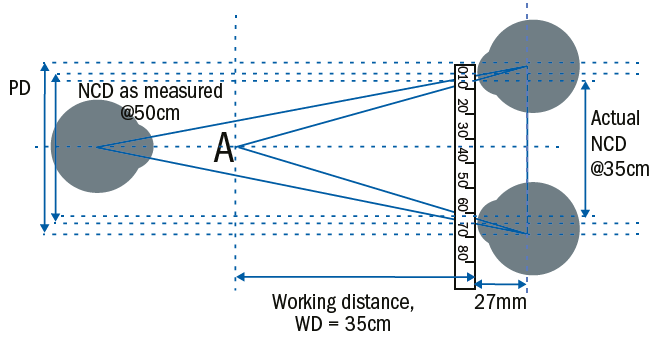
Figure 26: Error in NCD calculation
Fortunately for patients who purchase bifocal or varifocal spectacles this inaccuracy is academic since manufacturers decide on the inset (that is the difference between the mono PD and mono NCD) on the wearer’s behalf. This is partly because the inset can be calculated geometrically, but also because it must also be compensated depending on the power of the lens, hyperopes requiring greater insets than myopes, the theory of which will be covered in another article.
Conclusion
The research evidence shows that opticians are less than reliable at taking PD measurements and may be outside tolerance in as many as 50% of cases of certain high powered or progressive prescriptions. It is not clear why this is the case; however, an understanding of the basic geometry, better training and supervision, and a culture of double checking one’s own work by a different method would all help to provide better outcomes for patients. Asking the patient to look at a pen top or similar item rather than to look at your own pupil centre is a common and needless cause of error that should be avoided.
Opticians should ensure they have an adequate standard of near vision themselves to complete this demanding task, and where they have difficulties in closing one eye or have poor vision in one eye they should consider using a pupillometer of computer-based system instead. Finally, using an occlusion method for all children, hyperopes and strabismic patients will further improve accuracy.
Peter Black is a senior lecturer at the University of Central Lancashire and Immediate Past President and Chair of the Board of Directors of ABDO
References
- Walsh G, Pearce E. The difference between belief and reality for Viktorin’s method of inter-pupillary distance measurement. Ophthalmic Physiol Opt. 2009 Mar;29(2):150-4.
Further Reading
- Brookes C and Borish I. System for Ophthalmic Dispensing, 2007, 3rd edition, chapter 3.
- Wison D and Dara S. Practical Optical Dispensing, 2014, 3rd edition, chapter 4.
- ABDO College. British Standards Extracts, 2014, -103.
- Gilbert P. Ophthalmic Lens Availability, 2018, p330.
- Griffiths A. Practical Dispensing,2000, pp61-69. ABDO Publications
- Jalie M. Ophthalmic Lenses and Dispensing, 2000, pp39-42. BH.
- Obstfeld H. Spectacle Frames and their Dispensing, 1997, p29 and pp218-143. Bailliere Tindall
- Goersch H. Handbook of Ophthalmic Optics, 1991, 2nd edition, p284. Zeiss.
- Elliott D. Clinical Procedures in Primary Eyecare, 2003, pp162-165. BH
- Eskridge JB. Clinical Procedures in Optometry, 1991, pp39-52. Lippincott Williams and Wilkins