At present, frame measurements and measurements of the facial features that relate to the wearing of spectacle frames tend to be taught and examined separately, and as a result students and practitioners sometimes struggle to relate the two in a meaningful way. Until fairly recently, there has been a tendency for the number of measurements taken when dispensing to be minimal, the final fit of the frame being assessed purely visually, and any adjustments made without reference to any specific measurements. The trend towards offering many styles of frame, each in only one or two sizes rather than fewer models in a large number of sizes, has also contributed to the demise of the skill of frame measurements.
However, in recent years, the ability to take a wide variety of facial and frame measurements accurately, and an understanding of measurement systems, has become more important. Custom-made frames are showing something of a resurgence, using both traditional methods of manufacture from sheet acetate and also with the recent advent of reliable 3D printing technology. Custom lens shapes in rimless eyewear, and to a lesser extent with supra frames, have become much easier to do with remote
ordering systems and an understanding of the boxed lens system is essential to ensure the fit and cosmetic appearance is as expected. Free form lens technology is also driving the need to take additional face and frame measurements for sports eyewear, personalised progressive and compensated power single vision lenses.
The boxed lens (boxing) system
The system used for the measurement and description of frames internationally is the boxed lens (boxing) system described in BS EN ISO 8624:2011+A1:2015(E) which uses rectangles that contain each lens shape to determine the dimensions of the front of the frame (figure 1).
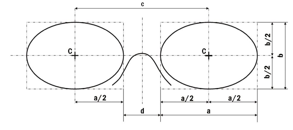
Figure 1 The box system of measuring spectacle fronts.
Key
C boxed centre
a horizontal lens size
b vertical lens size
c boxed centre distance (BCD)
d distance between lenses (DBL)
A line joining and extending beyond the centres of the rectangles (the box centres) is known as the horizontal centre line (HCL). When frame styling, that is helping a patient to choose a frame, it is common to align the frame HCL with the lower limbus (bottom of the iris)/lower eyelid and as such a line connecting the right and left lower limbus should be considered the facial version of HCL when measuring for a handmade frame in the traditional sense.
There are of course many exceptions to this, for example specifying a handmade half eye, making an extra deep frame, or when styling a classic round eye style where the pupil centre is required to be on box centre rather than 5 or 6mm above HCL as is typical of most frames designed in this way. In these cases, the facial HCL which is used to determine bridge measurements such as crest height will be different to the HCL that joins the box centres and becomes an individual feature of the design that must be translated into standard measurements to be properly understood.
In practice, we rarely refer to the British Standard terminology. The horizontal box size is usually referred to as the eye size and the DBL simply as the bridge. Both these measurements are universally printed on frames, usually in combination with the total side length.
The Frame PD
The box centre distance (BCD) is also commonly known as the frame PD and it can be seen from the diagram in figure 1 that:
BCD, c = a/2 + d + a/2 = a + d
Alternatively: Frame PD = Eye Size + DBL
The frame PD is an important concept when advising patients on their frame selection. As a rule, we never want the patient’s actual PD to be greater than the frame PD, otherwise the eyes are outset in the frame, and not only does this look odd but it also restricts the patient’s temporal field of view.
Frame Rules
Frame measurements are typically carried out with a frame rule. There are several of these available and each has been purpose designed to assist with the measurement of frames, each having advantages over the other for certain measurements (figure 2). The most popular frame rules are the ABDO Rule, the City Rule and the Serelo Rule which can be purchased from ABDO College Bookshop, Norville and a variety of optical equipment suppliers.
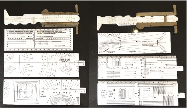
Figure 2: Photographs showing the two sides of four different rules: (from top to bottom), The Orthops Slide Rule (now sadly long discontinued and pictured here in the hope it may inspire reinvention); the ABDO Rule; the Serelo Rule; and the City Rule
Measuring BCD, Eye Size and DBL
A diagrammatic representation of the measurement of BCD, eye size and DBL is shown in figure 3.
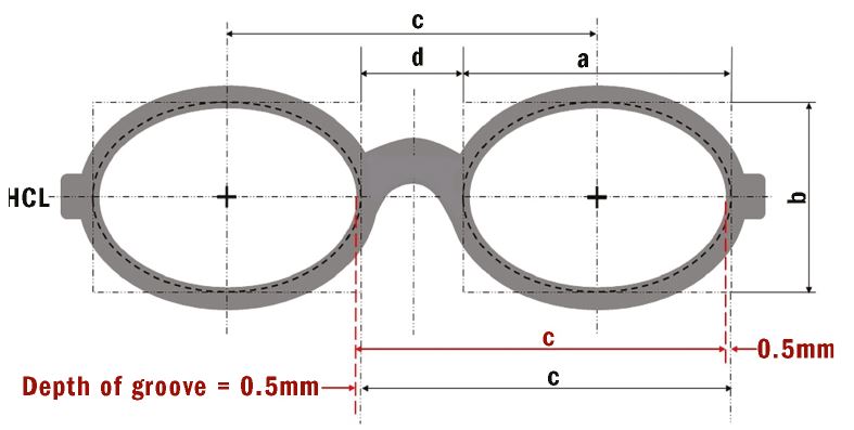
Figure 3: The box system of measuring frames showing the hidden nature of the lens shape and demonstrating that the lens is slightly larger (by approximately 1mm) than the lens aperture after allowance has been made for the groove in the rim/bevel on the lens
Note that the BCD (marked as c and shown in red) can just as easily be measured rim to rim without measuring from groove to groove. The DBL (marked as d), however, and the horizontal eye size (marked as a) are measured from the bottom of the groove and are typically 1mm different to what can be viewed, the DBL being smaller and the eye size being larger. Figure 4 shows use of a frame aligner for measurements and figure 5 use of the ABDO rule.
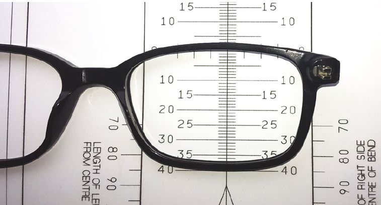
Figure 4: Measuring the vertical box height, b, using a frame aligner. 37mm is displayed, however the measurement is 38mm after allowing for the depth of the groove
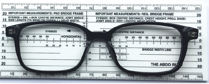
Figure 5: The ABDO Rule shows the BCD to the right measuring 70mm. There is no need to compensate for the groove as the L nasal and R temporal grooves cancel each other out. The eye size can be read to the left as 51½mm, and measures 52½mm allowing for the groove. The DBL shows as 18½mm, and measures 17½mm. The frame is stamped 52☐17 which is within tolerance
Decentration
Decentration (dec) is defined in BS 3521-1:1991 (01 203) as the ‘displacement, horizontal and/or vertical, of the centration point from the standard optical centre position’. Section 01 114 defines the standard optical centre position as ‘a reference point… situated on the vertical line passing through the boxed centre (or situated at the boxed centre if the manufacturer has published no contrary indication as to its height).’
In practice, if an order does not have a PD recorded, most labs assume that the practice wants the OCs to be placed at the boxed centre and will not query the order. Some labs have different standard optical centre positions. For example, children’s frames might be glazed with OCs at 3mm above HCL as a default setting (reflecting the fact that frames for young children tend to have deep b measurements relative to a and spend a lot of time looking up) whereas adult frames are glazed on HCL.
Keeping the frame PD close to the actual PD minimises the decentration of the lens and allows the smallest possible lens to be used. This in turn keeps the thickness to a minimum providing, for plus lenses, minimum sized uncuts are used, rather than edging down a standard diameter lens (figure 6).
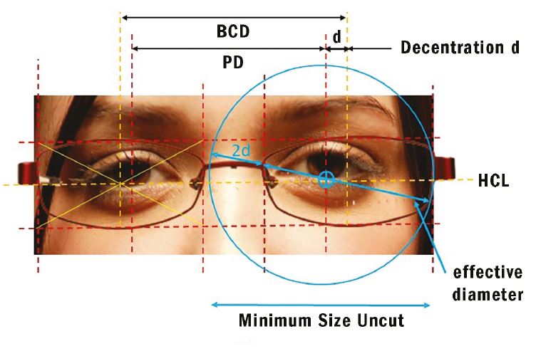
Figure 6: The measurements required for the calculation of blank size (minimum size uncut, MSU) using the formula: MSU = Effective diameter + 2(decentration) + 2mm
Minimum Sized Uncut
Minimum sized uncut (MSU) can be calculated simply from the formula:
MSU = Effective Diameter + 2xDecentration + 2mm to allow for glazing (see figure 6)
This method is reasonably accurate for regular shaped frames when the OCs are required to sit in the default position on HCL. Where the optical centre heights are required to be in a specific position as they are with aspherics, high powered lenses and progressives then a different method may be more appropriate, as shown in figure 7.
Figure 7: Measuring blank size accurately taking vertical as well as horizontal optical centre position into account. Here a mono PD of 32, height of 25mm, gives an uncut size of 65mm
Figure 8 shows the effect of matching frame PD (BCD) to the patient’s PD to minimise decentration (dec). On the right, before the patient’s left eye shows the effect of a frame that is too big for high powered lenses and requires an excessive decentration of 7mm. Before the patient’s right eye is a small oval lens shape requiring no decentration. At the bottom are realistic representations of what is possible in terms of saving thickness and weight providing the dispenser remembers to order minimum size uncut and not edge a stock lens.
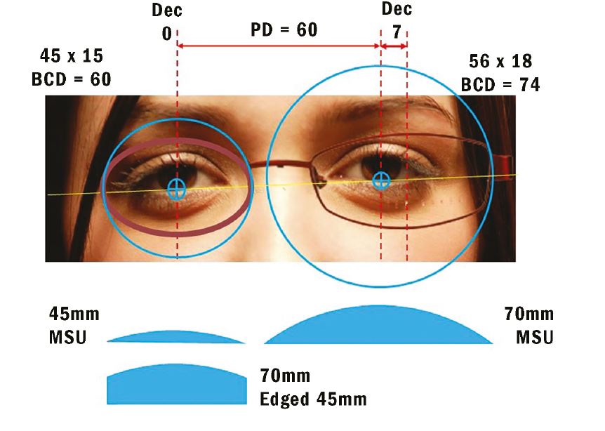
Figure 8: The effect of matching frame PD (BCD) to the patient’s PD to minimise decentration
Heights
The vertical position of the optical centre is most commonly measured to coincide with pupil centre, and this is entirely appropriate when dispensing progressive power lenses. However, placing the vertical optical centres on pupil centre is not usually appropriate when dispensing single vision lenses. Heights should be measured to pupil centre and then adjusted, usually downwards, to allow for pantoscopic tilt.
To measure heights to pupil centre on the patient, it is usual to measure from the lowest tangent of the lens shape (figure 9). Care must be taken not to measure to the rim immediately below the pupil as in pilot (formerly known as aviator) shapes this can lead to a measurement that is too small and will be misinterpreted by the lab who will always work to British Standards. To avoid doubt, it is wise to convert any vertical height measurement so that it is relative to HCL, after firstly making any necessary allowance for pantoscopic angle.
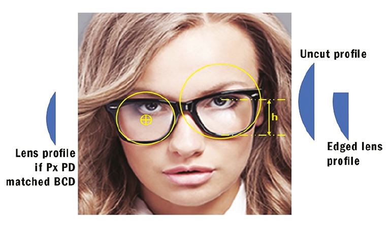
Figure 9: The measurement of height to pupil centre, h, from lowest tangent. Also shown to the right is the effect of placing the optical centres very high in a frame. In this case, a larger uncut may be required increasing overall thickness, and the edged plus lens has a very thick upper edge which is likely to be obvious to the onlooker and unsatisfactory to the patient
When measuring height to pupil centre, the optician must take care to ensure they are on eye level with the patient and that the patient is sat in a natural position. When dispensing multifocal lenses, it is also important to determine the patient’s head posture when, for example, driving and standing up as this may affect the performance of, and the patient’s satisfaction with, the lens.
Pantoscopic Angle
BS 3521-1:1991 01 116 defines pantoscopic angle as follows:
- The angle between the optical axis of a lens and the visual axis of the eye in the primary position usually taken to be the horizontal.
- The angle between the spectacle lens as worn and the vertical plane.
There is however much confusion about pantoscopic angle. A quick Google search should confirm that it is often confused with angle of side. There are several reasons for this:
- It is necessary to adjust angle of side to alter the pantoscopic angle.
- In the United States, the angle of side is known as the ‘frame pantoscopic angle’ and is often shortened to just pantoscopic angle to add to the confusion.
- Pantoscopic angle is often referred to as ‘pantoscopic tilt’ and assumes the bottom rim is closer to the face than the top rim. On the rare occasion when the top rim is closer to the face, such as with snooker spectacles and some baby’s frames, then the same measurement is properly termed the retroscopic angle and has a negative value.
Pantoscopic angle is important because, at the point where the visual axis (or the line of sight) passes through the optical centre of the lens, it must do so such that it coincides with the optical axis of the lens, passing through at right angles to the surfaces. Otherwise the patient is looking obliquely through the lens and any spherical power will effectively be changed to include unwanted cylindrical power. This phenomenon can easily be demonstrated by tilting a spherical lens on an automatic focimeter and seeing the resultant power reading change. Additional spherical power is also induced.
The amount of unwanted astigmatism and spherical power induced by failing to allow for pantoscopic angle can be calculated by the formulas:
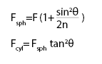
If we take a simple example of a +10.00DS lens sat with the optical centre on pupil centre (as many would have us believe is correct) and a pantoscopic tilt of 10°, and a refractive index, n, of say 1.50, then the induced prescription is as follows;
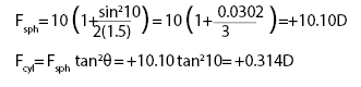
So, a +10.00D lens sat with the optical centre immediately in front of the pupil centre at a pantoscopic angle of 10 degrees has an effective prescription of: +10.10DS / +0.314 DC x 180 the cylinder axis being the same as the axis of rotation of the lens.
In other words:
+10.00DS on pupil centre @ Pantoscopic Angle 10° ≡ +10.10DS/+0.314 DC x 180 @ 0°
This explains why, when a patient cannot see quite so well out of their new spectacles as they expect to, a quick adjustment of pantoscopic angle one way or the other is often all that is required.
It is also interesting to note that the sphere power is dependent upon the refractive index, n, so the effect will be slightly less pronounced with a higher refractive index of say n = 1.76, although any benefit would doubtless be negated by the lower Abbe number and associated increase in chromatic aberration typical of higher refractive index lenses.
The rule of thumb formula P = 2h can be demonstrated, assuming the back vertex of the lens lies 27mm from the centre
of rotation of the eye, using the formula Tan P = h/27 and substituting a variety of heights or pantoscopic angles.
- If h = 4mm, then P = tan-1(4/27) = 8.36° ≈ 8°
- If h = 8mm, then P = tan-1(8/27) = 16.50° ≈ 16°
- If P = 5°, then h = 27 tan 5 = 2.36mm ≈ 2.5mm
- If P = 10°, then h = 27 tan 10 = 4.76mm ≈ 5mm
In other words, for single vision lenses, for every 2° of pantoscopic angle (tilt) you should drop the optical centres below pupil centre by 1mm, so for a typical frame where the tilt is 10° then the OC should be placed 5mm below pupil centre (see figure 10).
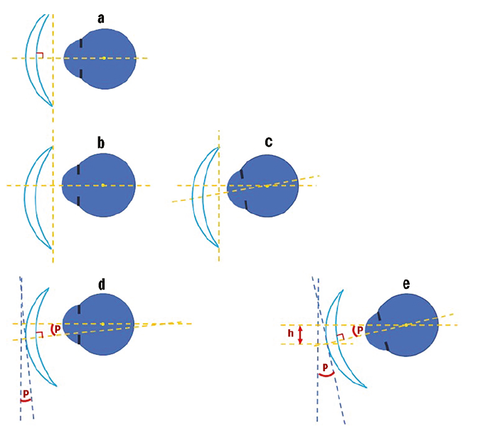
Figure 10: The relationship between vertical centration and pantoscopic angle.
a Shows the position of the trial lens during the sight test with the optical centre exactly on pupil centre and a pantoscopic tilt of 0°, ie the plane of the lens is vertical.
b The effect of positioning the optical centre on HCL with a pantoscopic tilt of 0°.
c The line of sight passes through the optical centre at an oblique angle causing aberrations.
d By angling the lens, the situation is improved though not perfect – P here refers to the ‘as worn’ pantoscopic angle which may be compensated for by altering the power of the lens.
e Applying the correct pantoscopic angle such that the line of sight is normal to the lens surface when it passes through the optical centre gives optimum lens performance. The lens is angled P°, and / or the optical centre is displaced downwards by h (mm), such that P = 2h
In the authors’ experience, failure to compensate for pantoscopic tilt is a significant cause of remakes and retests, yet many practitioners admit to hardly ever taking it into account. So why is it not more of a problem? The way frames are traditionally fitted with the eye sitting on HCL, such that the pupil centre is 5 or 6mm above HCL (where OCs are glazed by default), means that for a typical tilt of 10° the optical centres are, give or take 1mm, in the right place for optimum performance. However, with the fashion for large frames returning, it is prudent to bear tilt and vertical centration in mind especially when dispensing aspheric lens which are more sensitive to this issue (figure 10).
Measuring Pantoscopic Angle
In practice, it is impossible to measure an angle through the centre of rotation of the eye. However, assuming the primary position is horizontal, by similar triangles, we can see that the angle between the plane of the lens (that is a normal to the optical axis) and the vertical plane will give us an identical result.
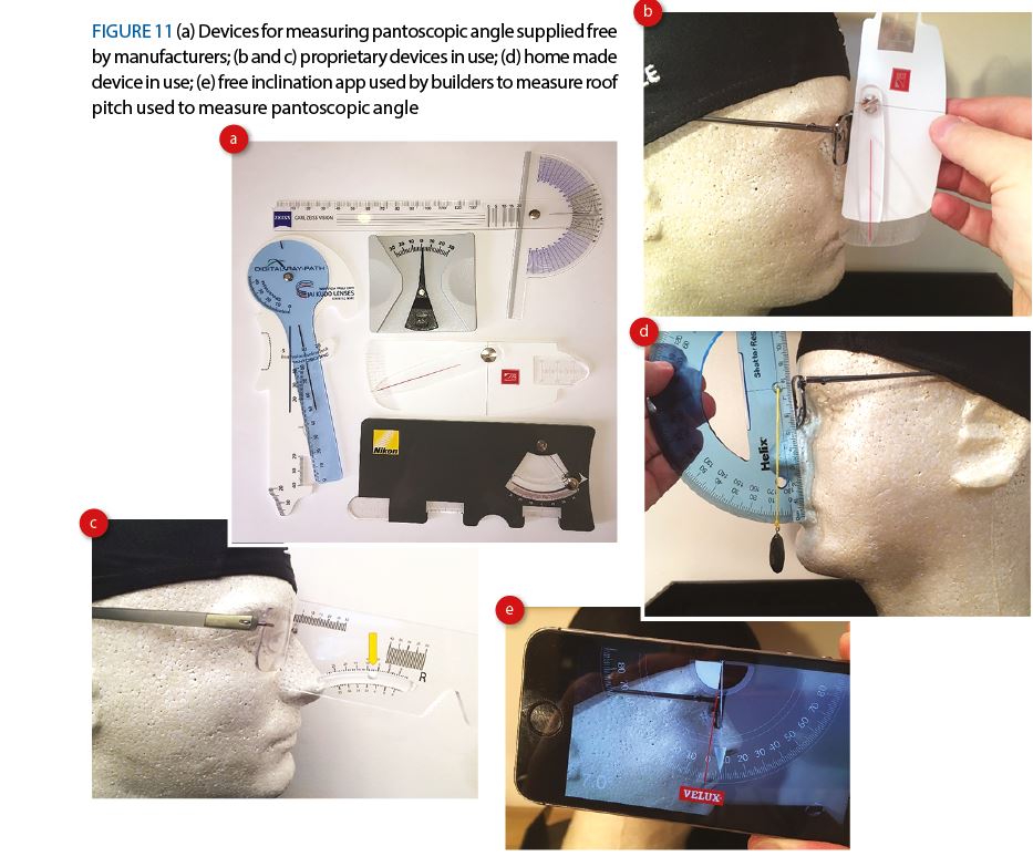
There are a great many gadgets for measuring pantoscopic angle, most of which are supplied free of charge by lens manufacturers. Additionally you could make your own, or even use a free inclination app used by builders to measure roof pitch (figure 11).
Angle of side
Side angle, or angle of side is defined in BS 3521: Part 2: 1991 as the ‘vertical angle between a normal to the back plane of the front and the line of the side when opened’.
Although pantoscopic angle and angle of side are related, comparing the measurements taken in figure 11e and figure 12 (which are for the same frame), it can plainly be seen that they are different measurements of 7½° and 12½° respectively. Figure 13 offers further diagrammatic explanation.
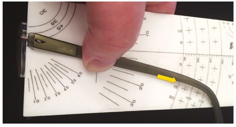
Figure 12: Angle of Side
Under normal circumstances pantoscopic angle will always be the same right and left (unless for example the bridge is twisted), whereas it is quite common for angles of side to be different if the patient has one ear higher than the other. Nevertheless, if it is required that the pantoscopic angle is increased by 5° then this is achieved by increasing the right and left angles of side by the same amount.
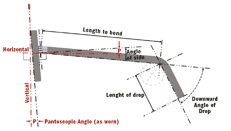
Figure 13: The difference between pantoscopic angle and angle of side. Also shown are other side measurements (to be covered in part 3 of this series)
Conclusions
Like the measurement of interpupillary distance, the matching of boxed centre distance to the PD and the measurement of optical centre heights in single vision lens dispensing is something that is taken for granted as being done correctly. Compensation of the pantoscopic angle to allow for optical centre heights can often be undertaken after the event. However, in many cases, an ‘as worn’ pantoscopic angle is the best that can be achieved rather than one that allows the optimum performance of the lens, particularly if it is aspheric.
The move to larger frames, especially those that are overly deep compared to previous fashions, and also the availability of compensated power lenses which enable such fashions to also be optically sound when previously they might have been a compromise, makes the measurement of pantoscopic angle, and the consideration of both vertical as well as horizontal decentration of critical importance if patients are to achieve the same effective prescription in their spectacles as they do during their sight test.
Peter Black MBA FBDO FEAOO is senior lecturer in ophthalmic dispensing at the University of Central Lancashire, Preston, and is a practical examiner, practice assessor, exam script marker, and past president of the Association of British Dispensing Opticians.
Tina Arbon Black BSc (Hons) FBDO CL is director of accredited CET provider Orbita Black Limited, an ABDO practical examiner, practice assessor and exam script marker, and a distance learning tutor for ABDO College.