The tendency to take minimal measurements when dispensing is in many ways counterproductive if opticians are to differentiate themselves from their online competitors. It is common to rely on assessing and adjusting the fit of frames ‘by eye’ in practice, and often with completely satisfactory results. However, simply observing spectacle wearers passing by in any public place demonstrates that often, due to poor initial frame selection, there is only so much that can be done to make a frame fit.
Excessive length of drop is the most prevalent of several commonly observed mistakes, the reasons for which are varied. No doubt poor frame range and design does not help, with sides often too long for the width of the front they are attached too, and then made so that they cannot be shortened, or in some cases even adjusted. Laziness or incompetence on the part of the person fitting the frame on collection also contribute where sides are not shortened when they easily could be or are bent in such a way that they do not grip the side of the head but project into thin air because the inward and/or downward angles of drop are insufficient.
Perhaps the biggest reason frames don’t fit is because they have been ordered online. The Bradford University team¹ point out that spectacles ordered online are three times more likely to fit so poorly they are unacceptable to the wearer and/or unsafe in the opinion of expert practitioners when compared to internationally accepted standards. As such, it is incumbent on opticians to always aim for perfect fitting spectacles; and the best place to start is to be mindful of what a good fit looks like, especially behind the ears. An easy way to ensure this is to measure key face and frame dimensions while dispensing to ensure nothing is overlooked and unsuitable frames are not dispensed. An added advantage of this is that the frame can be set up to near perfection in advance of collection, thereby minimising patients having to wait at what are often the busiest periods in practice (after school and at the weekend) when most patients appear to want to collect.
An understanding of the differences in measurements according to age, gender, overall body size and ethnicity also ensures that practitioners can keep a variety of frame fittings in stock to accommodate every patient’s needs. In the past many groups (large men, petite women, and small children whose mini-me adult frames did not fit) have been poorly served by the regression of frame sizes to the best-selling mean.
A knowledge of what works can also prevent practices being sold nice looking frames that are so poorly designed from an anatomical perspective they will never find an appropriate person to fit. There is currently a crop of frames from a leading designer brand with small eye sizes and un-adjustable rubber-like and carbon fibre composite sides that are so long that they barely fit any patient acceptably, let alone well, cannot realistically be shortened and only come in one length.
An understanding of the system used to measure, specify, design and fit frames is core to the competency of anyone involved in ophthalmic dispensing.
Frame styling
Helping patients to choose frames, rather than leaving them to their own devices, is a good start in reducing the incidence of poor fitting spectacles. Every dispensing optician can recount stories about when, against their better judgment, they allowed patients to choose frames for themselves and then had the almost impossible job of convincing them that the frame was inappropriate after they (or their significant other who has helped them choose) had fallen in love with it.
The rule of thumb is to place the eye on the horizontal centre line with the pupil centre placed on the vertical centre line of each boxed lens or decentred slightly nasally. In other words, the inter-pupillary distance is less than or equal to the frame PD, and the pupil centre is generally 4 to 6mm above HCL. As noted previously (see Optician 24.05.19), this allows an optimum and corresponding pantoscopic tilt of 8 to 12º so that the optical axis coincides with the visual axis when the eye looks through the optical centre (providing that the practitioner has ensured the centres are dropped 1mm from pupil centre for every 2º of tilt). The frame should also sit away from the brow and close to the cheeks, without resting on them uncomfortably, such that the patient cannot look beneath the lower rim. Even spectacle wearing icons adhere to this formula when their spectacles are studied closely.
Required measurements
At a recent CET discussion workshop, the question was posed, ‘what are the minimum measurements that should be recorded for a child?’. Predictably, delegates quickly came up with PD, and knew to match it to the BCD for minimum decentration.
Depending on the practice, some would further state the decentration or the minimum size uncut on the order. On high power lenses, everyone agreed that heights were essential. However, there was considerable disagreement between groups on how to measure heights. Pupil centre, 1mm below pupil centre, 5mm below pupil centre, and 1mm below pupil centre for every 2º of angle of side were all offered in good faith before the correct answer was forthcoming; namely, 1mm below pupil centre for every 2º of pantoscopic angle (tilt).
It should be possible to set the spectacles up at the point of verification such that they require minimal fitting when the patient attends to collect. So, what additional measurements should practitioners record at each dispense in order to achieve this? In the authors’ opinion, as a minimum, practitioners should record head width and length to bend and, while they must be mindful of length and angles of drop, temple width, side and pad angles. They will normally remain similar to the stock frame’s standard settings or will be changed appropriately as a consequence of the head width and side length being set. However, if it is deemed appropriate, then additional measurements should be recorded. If dispensing compensated power lenses, such as with sports eyewear, it is also important to ensure that the wrap (face-form angle) is also set correctly to that measured at the time of the dispense. Unlike pantoscopic angle, wrap can be set accurately without the patient present. Finally, vertex distance must be recorded on prescriptions over +/-5.00DS and may also be useful to consider in lower powers.
Head width
Head width is easily measured on the patient using head callipers or a face rule and frame rule together (figure 2). It is measured from ear point to ear point, in the groove between the ear and the skull at its highest point. It is worth investing in head/temple width callipers as the combination of face and frame rules is difficult to use except from above. Indeed, some patients (for example those wearing wigs, turbans, and certain hairstyles) can be difficult to measure from above and are best measured holding the callipers in front of the patient or from behind. Head callipers can be fashioned from tight joint engineers’ callipers, adapted for comfort with wooden or plastic beads. Once positioned the callipers stay in place and the separation of the beads can be compared to a ruler to obtain the measurement.
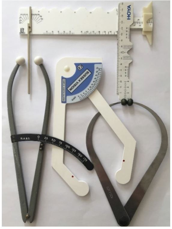
Figure 2: Instruments for measuring head and temple width
The facial head width (figure 3) corresponds to the uncompensated frame head width. To provide lateral grip, it is usual to compensate for the frame head width and make it 10mm or so less than the measured facial head width. The compensated head width, that is the measurement the frame should be set to, is defined as the distance between the sides at the ear points and, rather than using the facial measurement, could be determined by measuring the stock frame if it fits well at the time of dispense.
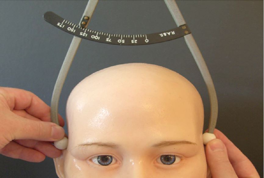
Figure 3: Head width, measured as 135mm
At this point, readers may be wondering why they should bother measuring the stock frame if they are sending it away or upstairs to the lab to be used from stock? The answer is because prescription lenses often do not have the same base curve as the frame’s dummy lenses. The curve of each rim, and consequently, the face-form angle (wrap) of the frame can be significantly changed. With high plus lenses, the wrap (or bow or dihedral angle) is dramatically increased, and with high minus lenses it is flattened, or even rendered negative (a so-called anhedral angle). Realigning the face form angle to where it needs to be (as close to zero as possible for standard uncompensated lenses, typically between 0 and +5º) will then likely alter the head width which will need to be readjusted too.
The difficulty in adjusting the lugs on some frames, especially plastics frames without backswept lugs such as the classic Ray-Ban Wayfarer, and many rimless mounts, can make such adjustments very difficult or even impossible. This has led to some manufacturers (such as Silhouette) supplying their own lenses to ensure that the frame/mount has the appropriate base curve and wrap whilst maintaining the correct head width (figure 4).
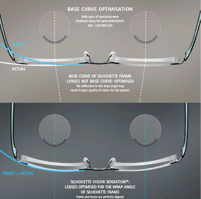
Figure 4: Rimless spectacles, showing the negative face form angle associated with glazing minus lenses with too flat a base curve. Correcting this also brings in the head width such that extensive, not to say difficult or impossible, adjustments are no longer necessary. Image courtesy of Silhouette
Head width is an important adjustment that is altered by increasing or decreasing the angle of let back (see figure 6), or, less satisfactorily, by applying (or removing) an inward curve to the side. How much pressure or grip will be applied is very much dependent on the design of the frame and the rigidity or flexibility of the bridge, lugs and sides. Frames with relative elastic bridges, including some memory metal and strip titanium frames, can fail to produce enough grip. Or the front bends at the bridge such that it has negative bow or wrap, which looks odd and affects the performance of the lenses. In such cases, the head width needs to be eased. However, the patient may never be happy with the fit of the frame if they feel as though they don’t grip well enough to stay in place.
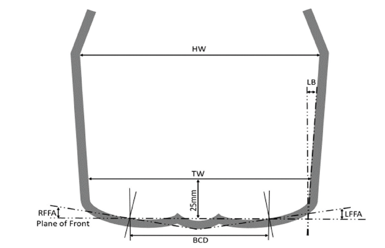
Figure 6: Head width (HW), temple width, (TW), angle of let back (LB) and boxed centre distance (BCD) for a frame with significant face form angle (wrap). Note, the plane of the front joins the vertical centre line of each boxed lens. RFFA and LFFA represent the right and left face form angle respectively
Head width is not usually an appropriate measurement when dispensing hinge-free frames/mounts, such as the Silhouette Titan Minimal Art/Icon. Many a final exam student has battled valiantly with the springy beta-titanium to set the head width to that measured on the patient, only to discover to their horror that the frame will no-longer stay on and the distance between ear points of close to zero was there by design.
Temple Width
Temple width is the distance between the temples on the patient (figure 5) and corresponds to, and should be less than, the distance between the sides 25mm behind the plane of the front (figure 6). It is important that the sides do not press on the temples or dig into the side of the head, and this measurement is most important to consider when making hand-made frames or custom rimless spectacles for a patient with a wide head and narrow inter-pupillary distance. Often such patients require custom-made spectacles because they have a strong prescription and require minimum decentration, so great care needs to be taken to specify adequately long lugs/overall front width to successfully accommodate these conflicting requirements.
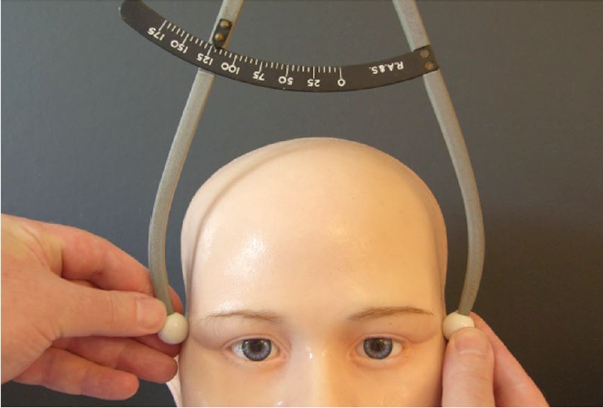
Figure 5: Temple width, measured as 120mm
Length to Bend
Length to bend (LTB) is defined as the distance between the dowel point and the ear point; the former being the centre of the bottom of the dowel hole (screw), the latter being the lower surface of the side where it touches the top of the ear, assumed on a drop end side to be the midpoint of an arc of contact between the bend of the side and circle which fits it. This is shown in figure 7, which also shows the difference between angle of side and pantoscopic angle, downward angle of drop, and length of drop (LoD). If measured correctly:
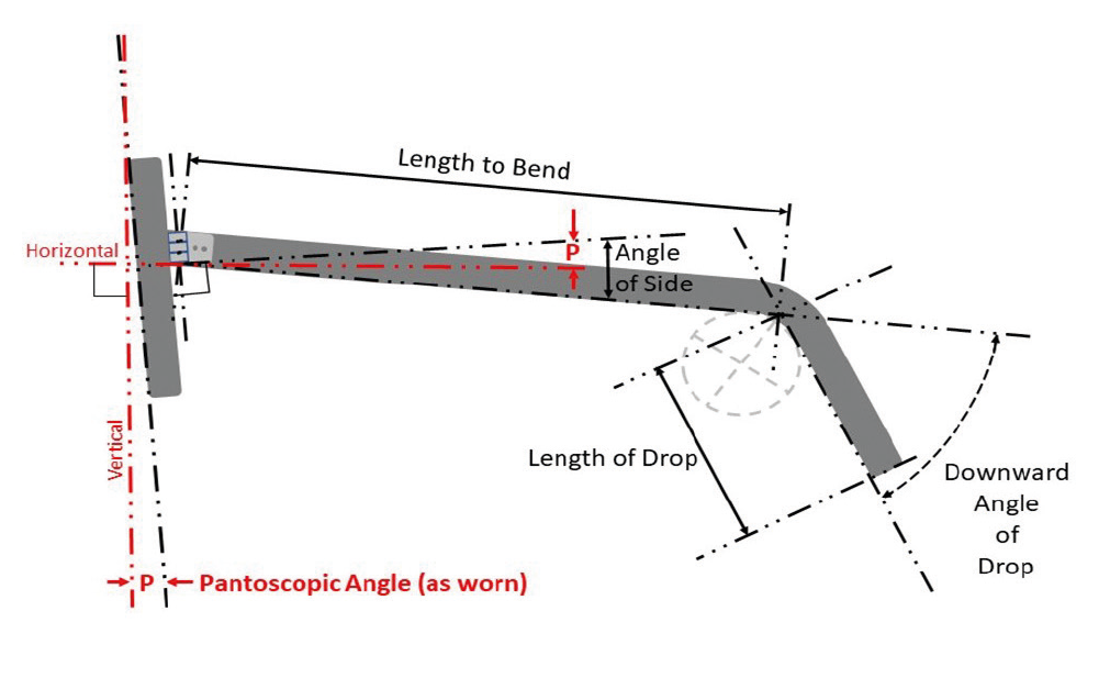
Figure 7: The difference between angle of side and pantoscopic angle (LTB + LoD = Total Side Length)
Total side length that is printed on the frame = LTB + LoD.
It has been shown in figures 7 and 8, and is worthy of note, that there is some disagreement between current standards. And whilst measuring along the centre line is entirely appropriate for total side length (length of drop plus length to bend in the diagram), it may not be accurate in terms of translation from a facial measurement. Better, in the authors’ opinion, to use the definition still in force in BS 3521: Part 2: 1991 which defines (in part 26 422) the length to bend as the distance between the dowel point (centre of the bottom of the dowel hole) and the ear point (the midpoint of the arc of contact between the bend of the side and the circle which fits it).
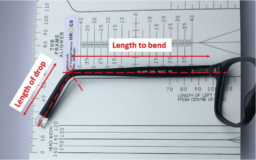
Figure 8: Measurement of length to bend, although to illustrate the method, the frame is held slightly to the left to show the ruler’s markings better. According to BS EN ISO 8624:2011+A1:2015, length to bend is measured along the centre line of the side from the centre of the bend to the centre of the midline of the joint which is located at around 96mm here though, if the frame was positioned correctly, would read 100mm. Note also, the frame details; DY 4608 is the model number, 3001 the colour, 52☐17 (eye size ☐ DBL) and 140 total side length
Given that in some optical examinations there is only 2mm tolerance, and given the disconnect between the more recent standard and how frames fit on the face, it would seem prudent for this measurement to be clarified, and exam tolerances relaxed a little; especially as with high joint frames with tapered sides, thick butt ends, and asymmetric tips, the two methods of measurement could easily differ by more than 2mm and both would seem to be correct to British Standards.
Face form angle
Face form angle is increasingly required to be measured in practice when dispensing sports eyewear, tailor made (personalised) progressive lenses and compensated power lenses. It is a feature of the frame and does not have a corresponding facial measurement, except that it alters the horizontal centration of the lenses. Face form angle is also known as bow, wrap angle, or dihedral angle, and is defined (in BS EN ISO 8624:2011) as the ‘angle between the plane of the spectacle front and the plane of the right lens shape or of the left lens shape’. It is negative if the temporal edge of the lens is further away from the head than the plane of the front.
Care needs to be taken measuring face form angle, as many gadgets are calibrated to take the average measurement and not each side individually. In the same way that pantoscopic tilt can change the effective power of a prescription so too can face form angle.
Revisiting the example of a +10.00DS lens sat with the optical centre inappropriately on pupil centre, for a pantoscopic tilt of 10º, and a refractive index, n, of say 1.50, the induced prescription was calculated to be: +10.10DS / +0.314DC x 180.
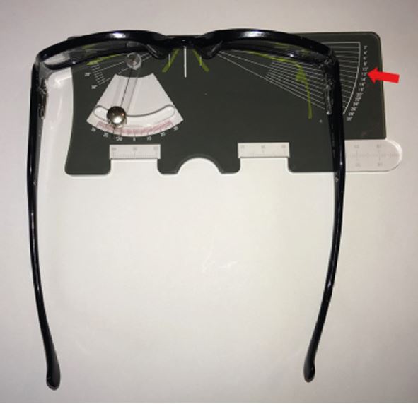
Figure 9: Left face form angle, measured as 12o
Considering these same lenses in a frame such as that in figure 9, with a wrap of 12º, then:
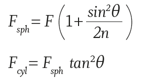
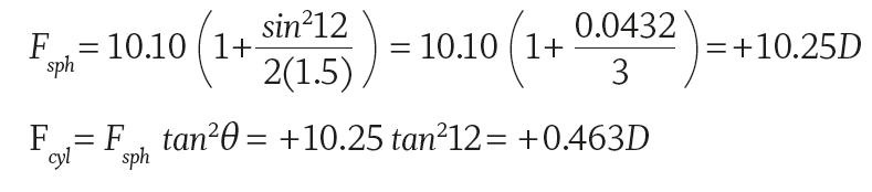
The resultant prescription, due to the change in face form angle, is +10.25 / +0.463 x 90.
Also, there is the original cylinder induced by the change in pantoscopic tilt; +0.314DC x 180.
Since two cylinders of equal power at right angles are equivalent to a sphere, this leaves +10.25DS combined with +0.314DS and a residual cylinder of +0.149DC x 90, so an equivalent
effective Rx of +10.55DS / +0.15DC x 90.
Any significant prescription dispensed with a significant face form angle also needs to be decentred in order to achieve the correct prismatic effect at the eye. BS EN ISO 13666:2012 17.5 defines the horizontal displacement of the centration point from the vertical centre line of the right or left boxed lens system, measured in the lens plane as:
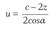
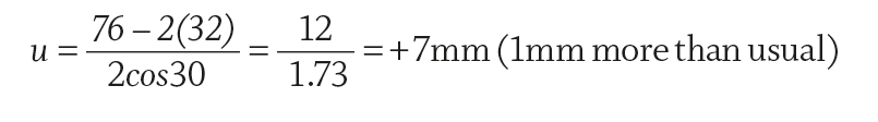
Where c is the boxed centre distance, z is the monocular centration distance, α the face form angle. We take a sports frame with BCD of say 76mm, and a face form angle of 30º, and a patient with a distance PD of say 64, then:
As-worn measurements – compensated powers
So far, it has been shown how incorrect vertical centration relative to pantoscopic tilt, and a failure to minimise wrap angle can induce significant changes in prescription. If the frame cannot be adjusted, the prescription will need to be compensated to ensure that the patient receives the correct effective power at the eye. For completeness, it is also necessary to consider the other major reason to compensate lens power; namely, the effect of changing back vertex distance.
Vertex Distance
Vertex distance is defined in BS EN ISO 13666:2012 5.27 as the ‘distance between the back surface of the lens and the apex of the cornea, measured with the line of sight perpendicular to the plane of the spectacle front’ (figure 10).
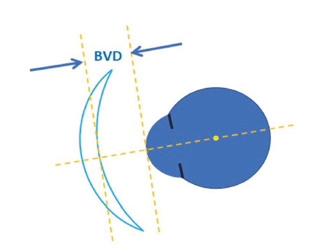
Figure 10: Vertex distance was formerly known as back vertex distance and is most often abbreviated as BVD on records
When a BVD is required, it has clear legal implications for retailers of spectacles. The General Optical Council (through its regulations Sale of Optical Appliances Order of Council 1984) states:
‘3.(3)(b)(i) the seller has checked … that BVD would be different to that indicated
3.(3)(b)(ii) … has made any adjustment necessary in the power of the lens to ensure that when in use it gives the optical effect required by the prescription…’
This document, which remains in force in 2019, must be read in conjunction with the Standards mentioned therein and their subsequent revisions and replacements so as to be clear on the regulations determining the rights and responsibilities of those, including online retailers, who choose to sell spectacles to non-restricted categories of patients in the UK; namely, adults who are not registered as sight impaired.
BS 2738-3:2004+A1:2008 is the relevant British Standard relating to the 1984 Sale of Optical Appliances regulations, though it should be read in conjunction with BS EN ISO standards 13666, 8429 and 8624 relating to spectacle lenses, optical instruments and spectacle frames respectively. BS 2738 relates to the specification of patient prescriptions and spectacle orders and states in section 4.1:
‘If the prescribed lens power is sufficiently high that the vertex distance becomes significant, e.g. if the power exceeds 5.00D then the distance at which the power was measured should additionally be recorded in the prescription. In order to calculate the required power of the lens, it is also necessary to record the vertex distance for which the prescription was recorded. This should be indicated by giving the vertex distance, in millimetres measured from the corneal apex, in the form, for example, ‘at 12’, following the prescription… This is intended to allow the person subsequently dispensing the spectacles or contact lenses to make any necessary adjustments to the power ordered.’
This has implications for optometrists, dispensing opticians and unregistered retailers of spectacles. Optometrists need to be careful to measure vertex distance and include it on any prescription that requires it. Otherwise, technically they have not completed the eye examination and are in breach of their statutory obligations. A BVD is required on any Rx where the power in the highest meridian, including any addition as applicable, is over +/-5.00D. This includes, for example, the Rx: +1.75 / +1.75 x 90 Add +1.75 which may surprise some practitioners.
Care should be taken measuring BVD with a trial frame as the scale assumes the rear slot will contain a lens, however for practical reasons, such as with very high simple astigmatism, this may not always be the case (figure 11).
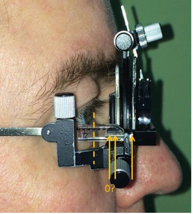
Figure 11: Measuring BVD with a trial frame
Where it has not been possible to measure BVD, for example when determining a child’s prescription by retinoscopy using hand held trial lenses, it is good practice to state this on the
prescription to avoid, for example, the dispensing practitioner having to contact the prescriber for non-existent information and wasting everybody’s time. It is also good practice to state whether BVD has been measured to the open or closed eye.
When dispensing, it is possible to measure the BVD with a ruler. However, this is a difficult measurement to take due to the curved nature of lenses and, especially with highly wrapped frames, the difficulty in ascertaining the position where the visual axis will intersect the lens surface. Indeed, practitioners may find it easier to measure the distance from the corneal apex to the front vertex of the lens and subtract the lens thickness which can be measured with thickness callipers or estimated at 1mm for dummy lenses (figure 12).
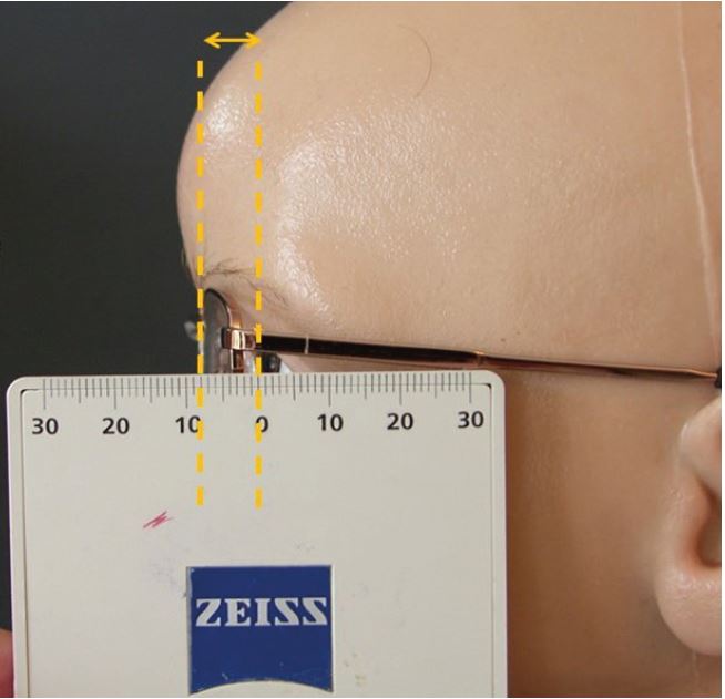
Figure 12: It may be easier to measure BVD to the front vertex of the lens and subtract the lens thickness. This can be measured with lens callipers, or assumed to be 1mm for dummy lenses. In this example: BVD = 8-1 = 7mm
It is generally considered that BVD measurement is easier to take with vertex callipers. There are two types:
- plastic ones – such as those supplied by Sussex Vision and require two handed operation
- metal ones (figure 13) – these can be operated with one hand
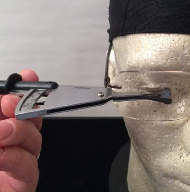
Figure 13: Metal vertex callipers (Hilco Distometer) in use
Care must be taken using callipers to ensure the patient does not open their eye at an inopportune moment as this may lead to ocular injury.
Consideration of vertex distance should not only apply to high powered lenses, as it has relevance to dispensing lenses of any power; especially progressives and bifocals. Increasing vertex distance will necessarily reduce field of view. This is an issue, particularly with progressive lenses, because the intermediate and near portions are already relatively narrow and are likely to have been narrowed further by an increased reading addition. So, an increased vertex distance can be a significant source of patient dissatisfaction, even in low powered lenses.
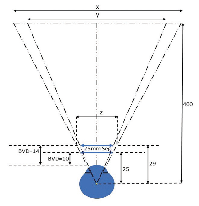
Figure 14: The effect on near field of view of positioning a 25mm bifocal segment 4mm further away
If we consider a D25 bifocal where the vertex distance is increased from, say, 10mm to 14mm (figure 14), then using similar triangles we can find x, the field of view at near with the segment at a BVD of 10mm:
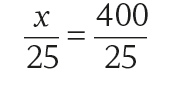
therefore x = 400mm
Moving the segment to a BVD of 14mm:
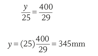
So, the effect of increasing BVD by 4mm is to reduce the near field by 55mm at a working distance of around 40cm. Another way of looking at this is to determine what size of bifocal segment, z, is required to maintain the patient’s near field of view, if the frame sits at 14mm instead of 10mm.
From the diagram, and using similar triangles:
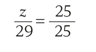
therefore z = 29mm.
So, if the vertex distance is increased from 10mm to 14mm and the patient has previously worn a 25mm segment they would need to increase to at least a 29mm segment to achieve the same width of near vision.
Using simple trigonometry, and assuming a nominal 15mm distance from the cornea to the centre of rotation of the eye (as in figure 14), the maximum field of view through the 25mm bifocal segment can be calculated to have reduced from 53.14º to 46.64º.
In fact, when allowing for the convergence of light through the positive powered segment, the field of view may be somewhat less than this depending on the addition and the power of the base lens. At a typical near working distance of say 40cm from the eye’s centre of rotation, this narrows the field of view by approximately 5cm. This will cause the patient to have to turn their head more when, for example, reading a newspaper.
Effective Power
The other area where vertex distance gains real significance is in high power prescriptions, where a difference between the vertex distance of the trial frame and the vertex distance of the spectacles may require the prescription to be altered to have the same optical effect at the eye.
There are several methods of compensating lens power. Perhaps the simplest is to draw out the position of the trial lens and spectacle lens relative to the eye as in figure 15.
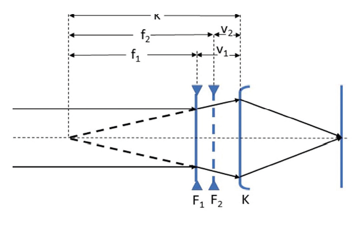
Figure 15: A reduced myopic eye of ocular refraction K, can be corrected by a lens of power F1 at BVD v1 or a lens of power F2 at BVD v2. It should be noted that k (the reciprocal of K) is equal to the sum of the focal length and BVD of each lens, k = f1 + v1 = f2 + v2
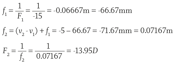
If we take a prescription of say F1 = -15.00DS at v1 = 14mm, and a new frame BVD v2 = 9mm.
Then:
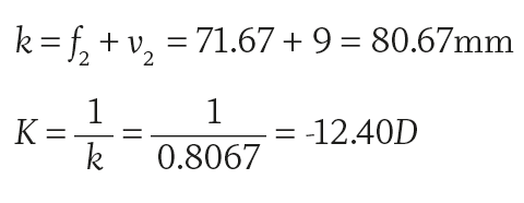
For completeness, to calculate the ocular refraction K, the power of a contact lens with vertex distance of 0:
Alternatively, there are two simple formulae:
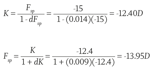
A third alternative is to ‘cheat’ and use a computer programme or one of the gadgets supplied with vertex callipers (such as the Vertex Distance Conversion Calculator shown in figure 16).
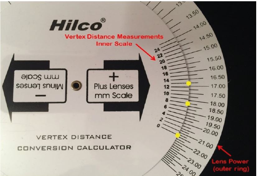
Figure 16: Vertex distance conversion calculator. Using the correct scale, the prescribed power is aligned with the trial frame vertex distance. In this case, the upper yellow dot shows +16.75D at 13mm. The new power is to be found aligned with the frame vertex distance. Here the middle dot shows an Rx of +18.25D at 9mm and the lowest dot shows a contact lens power of +21.50D
Given the frequency with which high powered prescriptions are provided without the required vertex distance, it is worth considering the effect of moving the lens without compensating the power.
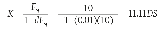
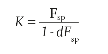
Considering the +10.00DS patient, if she was tested with a trial lens vertex distance of 10mm we can calculate that the ocular refraction, K, should be:
If the lens is fitted to a frame such that the vertex distance is 14mm instead of the prescribed 10mm then the effective power at the eye will be:
The patient is effectively over-prescribed by +0.52D. This would likely reduce the visual acuity of a patient whose best corrected VA was 6/6 down to 6/9 Snellen acuity.2
A catalogue of errors
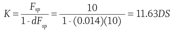
At this point it is also worth returning to the +10.00DS patient considered earlier, suffering the ill-effects of both a failure to compensate vertical centration for a 10º pantoscopic tilt and of the frame having a significant 12º face-form angle, which combined to give the effect of +10.55DS / +0.15DC x 90. Now, consider that the original +10.00DS was tested at 10mm and the frame the patient has selected fits at 14mm. To calculate the effective power K at the eye, we can use the following formula where d is the incorrect vertex distance and Fsp is the new lens power.
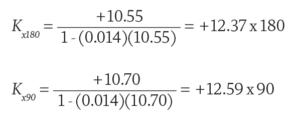
The effective power at cornea = +12.37DS / +0.22 DC x 90
It can be seen from this analysis that a failure to take into account even small changes in key measurements can combine to cause relatively substantial errors and lead to significant patient dissatisfaction. Here, the patient (K = +11.11D) is effectively over-prescribed by +1.25 / +0.25 x 90, an amount which any optometrist would consider as a significant change in prescription.
The same optometrist might argue as to the relevance of BVD on a prescription. However, this amount of error would almost certainly render a patient who is normally within the legal limit for driving to fall outside the standard and could have serious legal repercussions for both the patient and (potentially) the supervising practitioner.
Conclusion
When practitioners help patients choose frames, they should be mindful of the rules of thumb that guide the concept of a well-fitting frame, of the lenses that are to be glazed to the frame, and how this may impact the face-form angle, head width and overall ability to adjust the frame so that it fits.
As a bare minimum, it is recommended that side length to bend and head width are recorded at the time of dispense so that the spectacles can be properly set up prior to collection. Where face-form is likely to differ from the stock frame, or it has been specified in relation to compensated power lenses, it too should be recorded and aligned correctly.
At the collection appointment, most of the hard work will have been done, with still a need to check the pantoscopic angle relative to the heights and to fine tune the fitting of the sides and bridge. The next article will cover the remaining side measurements and bridge measurements for pad on arms, regular bridge and fixed pad frames and will begin to consider how frames are adjusted.
Peter Black is senior lecturer in ophthalmic dispensing at the University of Central Lancashire, Preston, and is a practical examiner, practice assessor, exam script marker, and past president of the Association of British Dispensing Opticians.
Tina Arbon Black is director of accredited CET provider Orbita Black Limited, an ABDO practical examiner, practice assessor and exam script marker, and a distance learning tutor for ABDO College.
References
- A Comparison of Spectacles Purchased Online and in UK Optometry Practice. Alderson AJ, Green A, Whitaker D, Scally AJ, Elliott DB. 2016; Optom Vis Sci., pp. 93(10):1196–1202. doi:10.1097/OPX.0000000000000955 .
- Tunnacliffe, A H. Introduction to Visual Optics. s.l. : ABDO, 1993.