The process of contact lens fitting requires comprehensive clinical assessment of the patient, including evaluation of refractive requirements along with a series of additional anterior eye measurements, together with assessment of corneal contour. This information, in conjunction with consideration of the patient needs and an anterior eye health assessment, will contribute to determining the ideal lens choice for each individual patient.
Refraction
As discussed in the last article (Optician 03.05.19), a valid refraction is a prerequisite for a contact lens fitting and if the patient is new to you, they should provide a copy of their results.1 Practitioners may opt to check this result prior to commencing a fitting, especially if some time has passed since their last eye examination. This can provide additional useful insight too for finer details, such as astigmatic axis and spherical refinement, for those patients sitting ‘between’ available contact lens parameters, or for those that require a best vision sphere lens where cylindrical correction is not available. Small checks at this stage may save future additional ‘tweaks’ to prescriptions. There are several key elements to consider when evaluating a refraction. A back vertex distance (BVD) measurement is required to be recorded on the prescription for refractions with a power of >±5.00 dioptres along either axis.2 However, it should be noted that dependent on BVD, adjustments may need to be made on powers of >±4.00 DS.
For those that prefer to do the calculations themselves, the formula shown in figure 1 can be utilised. However, there are many online calculators available and these, alongside BVD conversion tables, often serve as a quicker alternative. It is worth mentioning at this stage that BVD calculations must also be considered in the presence of an astigmatic refraction result.
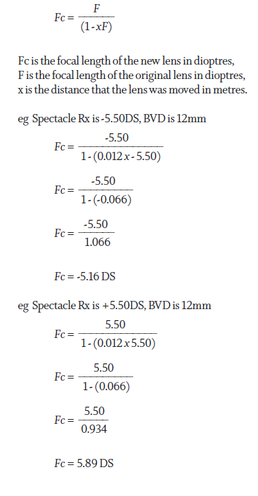
Figure 1: Calculation of contact lens power from spectacle prescription
A prescription of -3.75DS/-1.50DC x 180 may not at first glance look like it necessitates a BVD adjustment, however, it is important that each meridian is considered independently as this may influence the cylindrical power needed (figure 2). As a rule of thumb, when a prescription is written in negative cylinder form, a myopic patient will need the cylindrical power reduced whereas a hyperopic patient will require a cylindrical power increase.
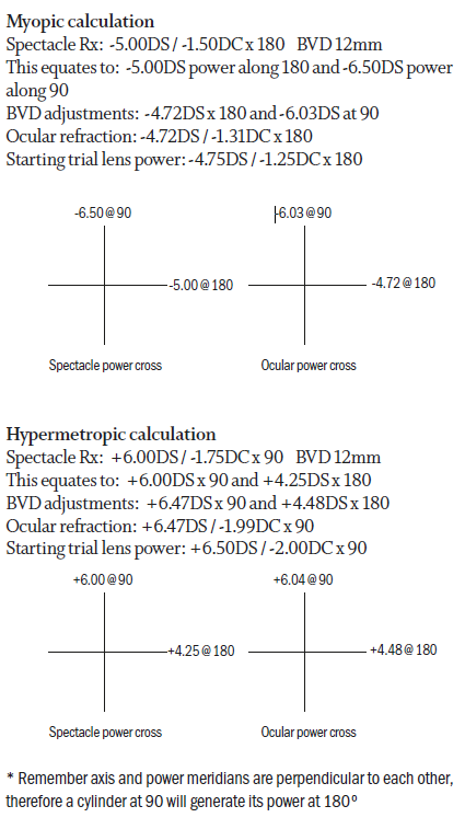
Figure 2: Calculation of contact lens power from a toric spectacle prescription, taking into account BVD
The presence of binocular vision anomalies will need to be considered when fitting a patient with contact lenses. Any prismatic correction provided in spectacles cannot be given in contact lenses so a discussion establishing expectations is critical here. Prism incorporated to assist a decompensating phoria may not be a contraindication depending on the needs of the patient and the tasks they wish to wear contact lenses for, prism incorporated to alleviate constant diplopia however, will be.
Details of visual acuity are not required on a spectacle prescription 2 so thorough questioning becomes invaluable in identifying amblyopia if you do not have access to eye examination records. Recording achievable visual acuity in the current spectacles can provide additional useful information here and provide a target acuity for contact lens wear. Amblyopia and binocular status become even more relevant when looking to fit multifocal lenses as many of these lens designs rely on near equal input from both eyes to allow for binocular summation and to achieve maximum success. Understanding and explaining the concept of spectacle magnification can be beneficial at this stage too, especially in high hyperopic prescriptions. Some patients benefit from ‘better’ acuity in spectacles due to the magnification provided by a plus lens. Any change in acuity that may result from a reduction in magnification is usually outweighed by an increase in the field of view that results from the closer proximity of the contact lens to the pupil. In addition, contact lens wearers will benefit from no roving ring scotoma or jack-in-the-box phenomenon, which is present with higher plus spectacle lenses. Myopic patients nearing presbyopia may need additional information about near expectations as the accommodative demand for close tasks is higher in contact lenses than that in spectacles.3 Conversely, hypermetropic patients will benefit from having to accommodate less and delay the need for a presbyopic correction. Attention to detail at this stage, considering how the spectacle prescription will translate into contact lens wear, provides a real opportunity to fully discuss and manage expectations.
Measurements
It has long been a topic of debate as to the relevance of certain ocular measurements, particularly in reference to soft lens fitting. The advent of ‘one-fit’ soft lenses meant that many practitioners adopted the ‘try it and see’ approach rather than considering in detail the measured values of various ocular parameters. While arguably, these measurements are more important in rigid gas permeable (RGP) and more complex lens fittings, understanding the impact to comfort from a poorly fitting contact lens, can highlight areas for improvement.
Horizontal visible iris diameter
Horizontal visible iris diameter (HVID) can be measured in a number of ways from the highly precise use of instrumentation such as topographers or use of slit lamp graticules, to simply measuring by eye with a conventional ruler (figure 3). It is important to note that it can be difficult to be highly accurate while measuring a curved surface with a flat tool and traditional ruler-based methods may underestimate the horizontal cornea by nearly 1mm. The value of this measurement potentially lies in initial lens diameter selection and provides an indication as to whether a soft lens diameter is sufficient to maintain full corneal coverage. An average HVID measurement is 11.8mm 4 and manufacturers of soft lenses will produce diameters designed to overlap the limbus by approximately 1mm each side for most patients. A patient falling outside of these ‘average’ parameters may experience difficulties with lens fit and this might, in turn, affect comfort or vision stability.
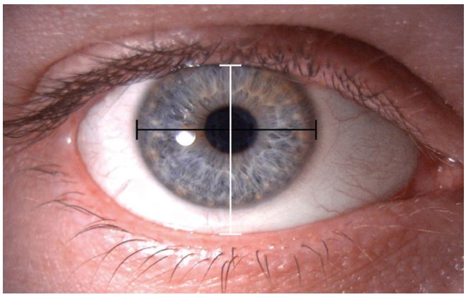
Figure 3: Measurement of HVID (black line) and VPA (white line)
Vertical palpebral aperture
Measurement of vertical palpebral aperture (VPA), is of questionable value in modern contact lens fitting. However, it may provide useful information for RGP and bifocal lens fitting if the position of the lids relative to the limbus is also considered. Assessing lid tension alongside VPA may however provide valuable information about ease of lens application and removal.
Pupil size
Measurement of pupil size becomes relevant when looking to understand the influence of lens geometry on visual outcomes, particularly when it comes to RGP lenses or in presbyopic lens fitting. In these situations, both average pupil size in ambient lighting and maximum pupil size, measured with a Burton lamp in a darkened room should be considered. The back optic zone diameter (BOZD) of a contact lens should be considered alongside pupil measurements, as there is an increased potential for visual problems, such as glare and haloes, if the pupil is larger than the BOZD. While a BOZD may be specified in RGP and more complex lens types, it will not be adjustable in most soft contact lens designs.
Assessment of corneal contour
Advancing technologies provide an increasing understanding of the relevance of corneal contour in contact lens fitting. These measurements can provide valuable data in the preliminary stages of fitting, but perhaps more importantly, they provide information for the ongoing monitoring of the effects of contact lens wear on the eye. Subtle changes in corneal contour induced by contact lenses or pathology can have a substantial impact on clarity of vision and may be indicators of problems to come. Significant changes in visual acuity or refractive correction can be induced by relatively small changes to corneal shape, hence the importance of using a sensitive and accurate method of measurement.
Keratometry
Use of keratometry, which typically measures the central 2-4mm of cornea, to select the initial soft contact lens base curve is based on the assumption that central corneal curvature is directly related to sagittal height, however, it is also related to other
factors, including corneal diameter, corneoscleral profile and corneal shape factor.5,6 It also assumes that the cornea is spherical, where it is typically a prolate ellipse, flattening gradually towards its periphery. It is therefore perhaps no surprise that several studies show no correlation between central or peripheral k-readings and the best fitting soft contact lens.5-7 However, the baseline data obtained by keratometry provides useful reference information and remains a common method of measurement in many practices. Assessment of mire clarity during assessment can provide valuable insight into tear film stability or corneal regularity and should be recorded alongside keratometry readings (table 1, figure 4).
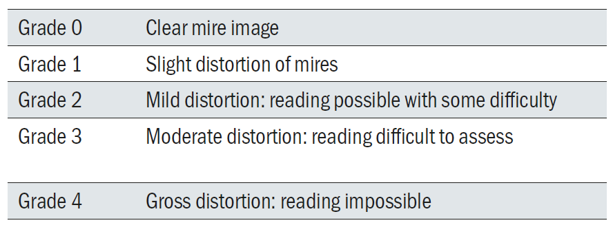
Table 1: Grading of mire distortion
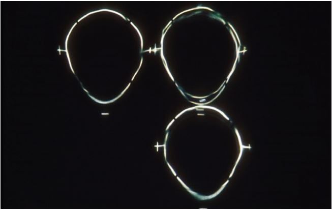
Figure 4: Bausch & Lomb one-position keratometer showing mire distortion
Keratometry works on the principle of recording the image size reflected from a known-sized object. Given the object size and distance from image to object, the radius of curvature of the cornea can be calculated. In manual keratometry, measurement of corneal curvature is achieved using an optical doubling system where the observer aligns images of mires reflected from the cornea. This doubling may be ‘fixed’ as in the Javal-Schiotz instruments, or variable as in the Bausch & Lomb style instrumentation. Often referred to as ‘one-position’ (variable doubling) or ‘two-position’ (fixed doubling) instruments, there are advantages and disadvantages to both. In a one-position instrument such as the Bausch and Lomb Keratometer, readings from two principle meridians can be taken at the same time so it may be quicker (figure 5).
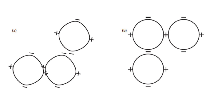
Figure 5: Bausch & Lomb one-position keratometer mires: (a) mire and axis misalignment, (b) mire alignment
However, it does assume that these two meridians are perpendicular to each other. The two-position, fixed doubling instruments have a longer working distance so can be more accurate and can also identify and measure irregular meridians. Using these instruments requires correct eye-piece focusing as errors in this leads to incorrect measurements of corneal curvature. Calibration is also necessary and this is achieved using calibration steel ball bearings of known curvature that are accurate to ±0.001mm.
Keratometry may also be obtained electronically, typically in conjunction with autorefraction. These systems are usually two position instruments which utilise servomotors (a motor coupled with a sensor for position feedback) to drive the doubling device until alignment can be assessed optically using light emitting and detecting diodes. These devices typically provide a mean of three measurements and may provide an estimate of the corneal shape by measuring the corneal radius peripherally as well as centrally.
Obtaining results from any method is only part of the process; interpreting the measurements accurately is what can facilitate contact lens fitting. Table 2 shows the range of K-readings in a normal population, with averages around 7.70 to 7.90mm, or 43 to 44D. Falling outside of these parameters would indicate a steeper or flatter than average central cornea. Typically, a myope will have steeper keratometry readings than a hyperope. 8 Keratometry measurements are useful in evaluating astigmatism and can provide valuable information as to whether astigmatism is corneal or lenticular. With the rule astigmatism is when the steepest axis is vertical (or within 30º) creating a negative cylinder axis at 180. In against the rule astigmatism, the steepest axis is horizontal leaving a negative cylinder axis at 90º. When the two meridional measurements are compared, this can indicate the amount of corneal astigmatism, with 0.1mm difference equating to approximately 0.50DC of astigmatism. This information can be used to help select the best design and type of lens to correct astigmatism, particularly when it comes to RGP contact lenses.
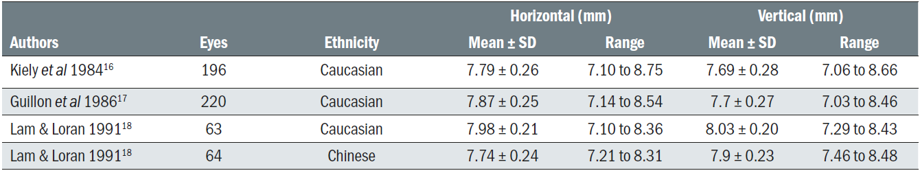
Table 2: Range of K-readings in normal population
Corneal topography
When more information about the shape and curvature of the cornea is required, for example to facilitate fitting of complex RGP lenses or in orthokeratology, corneal topography will provide a more detailed description of the corneal characteristics. While a keratometer will measure the radius of curvature across the central 2 to 4mm of the cornea, corneal topography traditionally analyses and measures between 9 and 10mm of the cornea, generating a topographic map of the corneal shape. Topographers are now available to map the whole of the anterior surface of the eye, which can be particularly helpful in large diameter rigid lens fitting.
Gross corneal topography was first assessed by Placido in 1880 by projection of a simple concentric ring target onto the cornea.9 Many modern day topography systems continue to use the technique of Placido disc projection to measure corneal curvature, with information captured using specialised video systems. With the use of computer-aided software and the capability to translate the information captured by the camera into useful information on corneal shape, these systems are also referred to as videokeratoscopes.
Placido disc/ring based topographers use the tear film as a convex mirror to reflect a series of concentric rings (figure 6).9 Corneal shape is assessed by analysing the regularity and separation of the reflected rings to give curvature and power information. Placido disc based systems do not obtain true corneal height information. This type of topography requires a good quality tear film to ensure accurate measurement, therefore it is advisable to ensure the patient had a good blink immediately before capture. Alternatively, ocular lubricants can be used to improve a poor quality tear film.
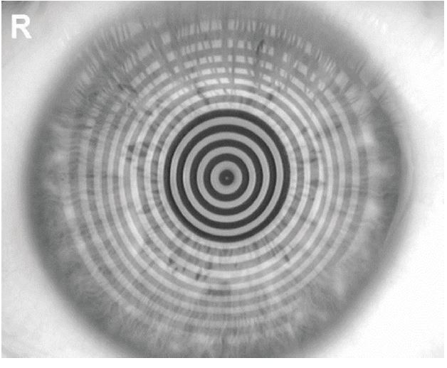
Figure 6: Placido disc topography, with the Topcon CA800
Corneal tomography
While corneal topography can only gather information about the anterior corneal curvature, corneal tomography can also gather posterior corneal information, by examining cross sections of the cornea. The Oculus Pentacam combines a slit projection system with a Scheimpflug camera, which rotates around the eye (figure 7).10,11 The cornea is illuminated with a slit of light, causing back scatter of light which is captured by a camera, oriented according to the Scheimpflug principle, thus creating a perfectly sharp image. A series of radial images are captured around the eye, then combined to create a three-dimensional model of the entire anterior portion of the eye from the anterior lens to the anterior corneal surface. The rotating measurement principle used in Scheimpflug imaging avoids measurement errors that would result from horizontal scanning. Captured images are mathematically analysed to generate data on elevation, curvature and pachymetry.10
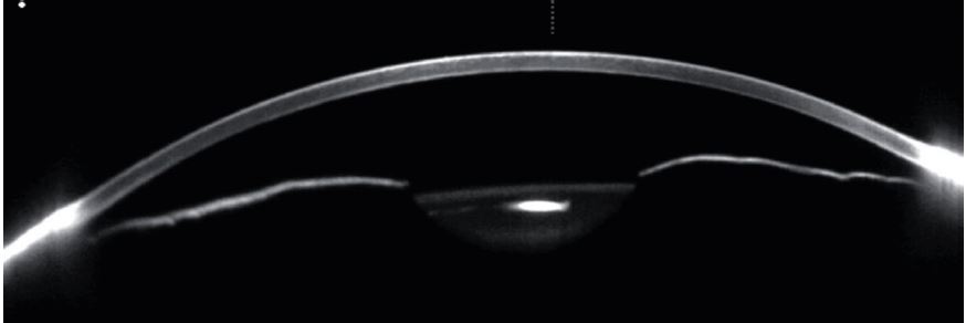
Figure 7: Slit projection, Scheimpflug tomography with the Oculus Pentacam
Topography and tomography interpretation
As with any technique, the real skill lies in interpreting the information gathered. Corneal topographers, using sophisticated software, are able to present results in a range of different forms including colour coded maps, 3D images and corneal cross sections. The most commonly used maps are the curvature and elevation (height) maps, each of which will be briefly described below.
Curvature maps display the cornea’s radii of curvature and can be expressed in either mm or dioptres. Colours are used to represent the curvature and dioptric value across the cornea, with hotter colours (reds and oranges) representing steeper areas, and cooler colours (blues and greens) representing flatter areas. It is worth noting whether an absolute or normalised scale is being used to display results as this will have an impact on the pattern observed. The absolute scale uses large, fixed intervals to cover the whole scale of possible curvature values, with the same scale and colours used for all eyes. While the absolute scale can mask fine details, it should always be used to facilitate comparisons over time. The normalised scale is not fixed and varies for each eye and image. The range for the normalised scale is determined by the flattest and steepest values of the cornea it is examining. While this scale reveals fine corneal detail, care should be taken when using it as small details can appear to be magnified by an inappropriately narrow scale (figure 8).12
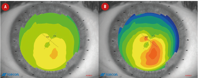
Figure 8: Axial curvature maps showing irregular astigmatism, which is revealed in the normalised scale (B), but masked in the absolute scale (A)
Corneal curvature can be calculated, and thus displayed in two ways; axial and tangential. Axial (global/sagittal) radius of curvature measures the curvature of each section of the cornea in relation to the optical axis (figure 9A).
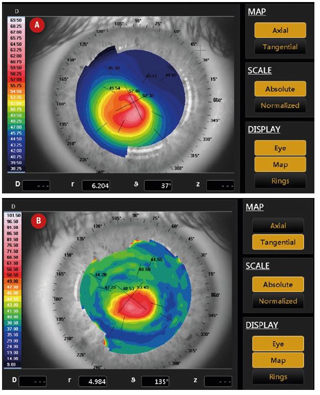
Figure 9: Curvature maps of a keratoconic eye. While the cone can be seen in the axial map (A), the tangential map (B) allows better localisation and more detail
This results in measurements having a spherical bias and being inaccurate in the periphery and in irregular corneas.13,14 However, as these maps produce large, diffuse patterns they are better for visualising regular corneal astigmatism, for contact lens fitting and for estimating the general corneal curvature. Axial curvature maps of normal corneal topography can be classified into five groups: round, oval, symmetrical bow tie, asymmetric bow tie and irregular (figure 10).15 Tangential (local/instantaneous) radius of curvature measures the curvature of each point on the cornea with respect to its neighbouring points (figure 9B). Therefore, tangential mapping is more accurate for local irregularities and for mapping the peripheral cornea curvature.12,14 Tangential maps should always be used over axial maps in detection and monitoring of keratoconus as they allow more accurate assessment of the cone location.

Figure 10: Classification of corneal topography map showing (from left to right) round (spherical cornea), oval, symmetrical bow tie (regular astigmatism), asymmetric bow tie (irregular astigmatism) and irregular patterns, as described by Brogan et al.15
Height maps can be approximately generated from Placido-based topographers but can only truly be created from a projection-based system. Rather than displaying the raw data, it is typically illustrated in reference to a known sphere shape.15 In elevation maps, hot colours represent elevation above the reference sphere (flatter curvature), while cool colours represent areas lower than the reference steeper (steeper curvature) (figures 11 and 12). Elevation maps can be useful for RGP fitting. When the reference sphere is set to the BOZR of the contact lens, warm colours would show where the fluorescein would be displaced, whilst the cool colours demonstrate where fluorescein would be expected to pool.
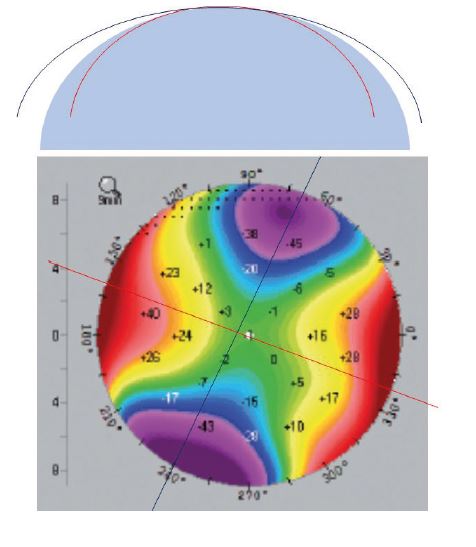
Figure 11: Elevation maps. A diagrammatic depiction of elevation maps, described in relation to a best-fit-sphere (top). The steep meridian (red) is below the best-fit-sphere, and the flatter meridian (blue) falls above the best-fit-sphere. In the elevation map (bottom), the flatter meridian is seen as elevated above the best-fit-sphere (warm colours), whilst the steeper meridian is seen as below the best-fit-sphere (cool colours).
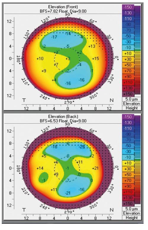
Figure 12: Elevation maps for a normal astigmatic cornea. The front surface (top right) and back surface (bottom right) elevation maps show elevation above the reference sphere across 110o
Summary
When commencing a contact lens fit, refractive information must be carefully assessed to ensure the correct contact lens power is selected, with BVD calculations applied for each meridian once the spectacle refraction is over ±4.00DS. While assessment of corneal curvature using keratometry is now thought to offer little help with selection of an appropriate soft contact lens, the College of Optometrists guidance suggests keratometry or topography should be completed during a fitting assessment. Despite its potential limitations within the fitting process of soft contact lenses, understanding and monitoring corneal curvature is vital in contact lens practice to monitor for corneal changes and keratometry continues to provide accurate and reliable results for many practitioners. Where more specialist contact lens fitting is required, corneal topography or tomography can provide a wealth of information which is often vital to achieve a successful outcome for the patient.
This article is part of a revised and updated ‘Essential Contact Lens Practice’ series, originally authored by Jane Veys, John Meyler and Ian Davies. This article was produced without further input or review from the original authors.
Clair Bulpin is an optometrist, assessor and examiner for the College of Optometrists and a paid consultant faculty member for the Johnson & Johnson Institute, UK. Dr Rachel Hiscox is a Professional Education & Development Manager, UK & Ireland for Johnson & Johnson Vision Care.
References
- College of Optometrists Guidance. Available at: https://guidance.college-optometrists.org/guidance-contents/knowledge-skills-and-performance-domain/fitting-contact-lenses/ Accessed March 2019
- British Standards. British Standards Number 2738-3:2004, A1:2008. Available at https://www.college-optometrists.org/the-college/library-and-information-services/online-databases-and-reports/british-standards-online.html to The College of Optometrists Members. Accessed June 2019
- Jiménez R, Martínez-Almeida L, Salas C, Ortíz C. Contact lenses vs spectacles in myopes: is there any difference in accommodative and binocular function?, Graefes Arch Clin Exp Ophthalmol, 2011;249(6):925-35
- Caroline P, André M. The effect of corneal diameter on soft lens fitting, part 1. Contact Lens Spectrum. 2002;17(4)56.
- Gundal R, Cohen H and DiVergillo D. Peripheral keratometry and soft lens fitting. Int eyecare. 1986; 2:12 611-613
- Young G Schnider Hunt C Efron S . Corneal topography and soft contact lens fit. Optom Vis Sci. 2010;87:358–366
- Young G. Ocular sagittal height and soft contact lens fit. J BCLA, 1992;15:1 45-49
- Lourdes Llorente, Sergio Barbero, Daniel Cano, Carlos Dorronsoro, Susana Marcos; Myopic versus hyperopic eyes: axial length, corneal shape and optical aberrations. Journal of Vision 2004;4(4):5. doi: 10.1167/4.4.5.
- Mejía-Barbosa Y, Malacara-Hernández D. A review of methods for measuring corneal topography. Optom Vis Sci. 2001;78(4):240-53.
- Belin MW, Khachikian SS. An introduction to understanding elevation-based topography: how elevation data are displayed - a review. Clin Experiment Ophthalmol. 2009 Jan;37(1):14-29
- Konstantopoulos A, Hossain P, Anderson DF. Recent advances in ophthalmic anterior segment imaging: a new era for ophthalmic diagnosis? Br J Ophthalmol. 2007;91(4):551-7
- Corneal topography. American Academy of Ophthalmology. Ophthalmology. 1999;106(8):1628-38
- Sinjab M. A Guide to Interpreting Corneal Topography. Cataract and Refractive Surgery Today Europe. Jan 2012: 20-24
- Sinjab M. Skillful interpretation of Corneal Imaging. Cataract and Refractive Surgery Today Europe. April 2014: 68-72
- Bogan SJ, Waring GO, 3rd, Ibrahim O, Drews C, Curtis L. Classification of normal corneal topography based on computer-assisted videokeratography. Archives of ophthalmology (Chicago, Ill : 1960). 1990;108(7):945-9
- Kiely PM, Smith G, Carney LG. Meridional variations of corneal shape. Am J Optom Physiol Opt, 1984;61(10):619-26
- Guillon M, Lydon DP, Wilson C. Corneal topography: a clinical model. Ophthalmic Physiol Opt. 1986;6(1):47-56
- Lam CSY, Loran DFC. Designing contact lenses for oriental eyes. Journal of the BCLA, 1991;14(3):109-114