This article will discuss the remaining face and frame measurements not covered thus far in the series, those that are traditionally largely related to hand-made frames and form a key aspect of dispensing opticians’ and optometrists’ preliminary and final qualifying examinations. Being mindful of these measurements as features of all frames assists in appropriate frame selection where a patient does not require custom made frames but nevertheless has facial features, such as a low or high bridge, that present a challenge when dispensing from a typical stock frame range.
Pareto Principle
The Pareto Principle, otherwise known as the 80:20 Rule, says that 20% of causes inevitably produce 80% of effects. This statement has stood up to serious economic scrutiny, though it is not mathematically precise, sometimes being nearer 70:30. In optics, the 80:20 rule abounds; 20% of contact lens products produce 80% of sales, 20% of patients deliver 80% of operational profits, 20% of frame/lens/contact lens/companies control 80% of the market, and so on.
The 80:20 principle might also be applied to the work of dispensing opticians who use 20% of their knowledge (the proportion of their knowledge that is taught to optical dispensing assistants) to deal with 80% of patients. It might further be reasonable to argue that 20% of patients have needs that are more complex than the average. However, the optician’s patient and practice colleagues may be completely unaware that a little-known dispensing skill might be required.
For example, when fitting single vision spectacles, the optician might leave the optical centres marked on high powered or aspheric lenses and tilt the patient’s chin back until the plane of the front sits vertically. At this point, they would expect the optical centre to coincide with the exact pupil centre if the PD has been measured correctly and the heights have been correctly compensated for pantoscopic tilt. If in this position the optical centre is above the pupil centre, then the angles of side (and therefore pantoscopic angle) need to be increased accordingly until the optical centre is appropriately positioned.
The problem is that patients and colleagues cannot see what is going on inside the optician’s head. The only way to counteract this is to give a running commentary of what is being done. This applies throughout professional practice including clinical examinations. In the authors’ experience, when assessing and on occasion acting as patients for student physician associates during Objective Structured Clinical Examinations (OSCEs), communicating both the thought processes and the actions being carried out provides the patient with reassurance, and the examiner with additional proof, that the practitioner knows what they are doing.
Hand-made frame measurements fall decidedly within the 80% of dispensing knowledge that is required to assist the 20% of patients whose needs are more complex. That said, a failure to understand the system used to measure, specify, design and fit frames, can result in poor quality dispensing outcomes for any patient whose facial anatomy or prescription requirements deviate even slightly from the average. It should also be remembered that custom eyewear is very much on the increase both in the UK, with half a dozen manufacturers exhibiting at UK trade shows this year, and abroad (figure 1).
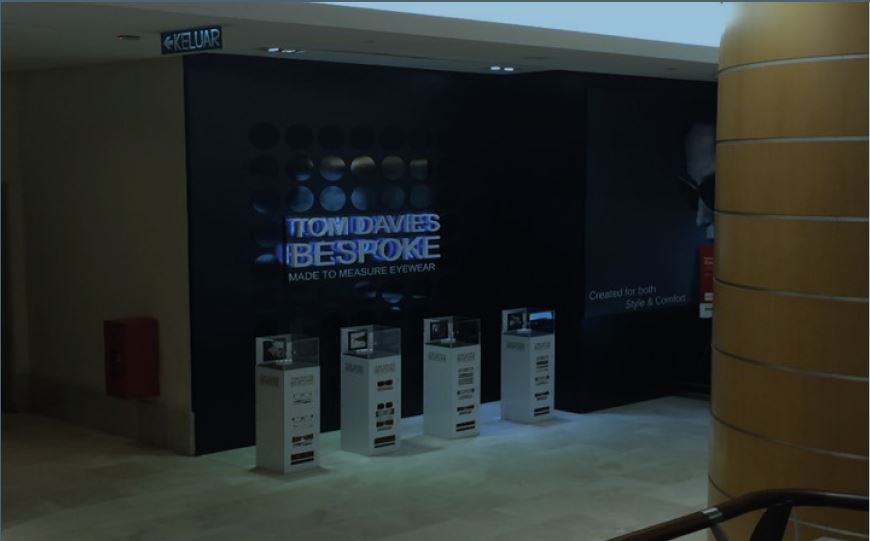
Figure 1: Custom made eyewear is very much in demand, as seen here in a Malaysian business centre
This article builds upon the frame styling rule of thumb: to place the eye on the horizontal centre line (HCL) with the pupil centre placed on the vertical centre line of each boxed lens or decentred slightly nasally. It introduces other significant reference lines used in frame design, namely:
- the vertical line of symmetry through the bridge
- the bridge width line positioned 5mm below the HCL
The facial measurements required for translation to frame measurements to make a hand-made spectacle frame remain a key part of a dispensing optician’s training and education. While it is not a daily occurrence for most dispensing opticians or optometrists to take these measurements, they remain features of frames that opticians must be mindful of at every dispense.
When we say a plastic frame sits too low, we probably need to find an alternative with a lower crest height or bridge height. When we say a frame is too tight on the nose, we may look for a wider distance between rims, or alternatively a larger apical radius. When a bridge appears too splayed, it may be that the bridge width is perfect but we need a steeper frontal angle and/or splay angle of pad for the bridge to fit well. When the lenses touch the patient’s lashes, we might increase the vertex distance by making the bridge projection less positive or more negative. When we see, as we so often do, end tips that project into thin air behind the ears, neither contouring the back of the ear nor providing lateral grip on the side of the head, then we know to adjust both the downward and inward angles of drop.
The face and frame measurements previously covered (or mentioned in italics above) alongside a few measurements relating to adjustable pads on arms and curled sides, cover almost all those that student dispensing opticians/optometrists are required to be able to measure for their exams, and that qualified registrants should remain competent with. They may take relatively few of these measurements regularly. However, understanding how measurements of the face relate to the frame, the lenses it holds, and the appearance, comfort and vision of the patient cannot be underestimated.
Hand-made frame measurements
In the authors’ experience, the need for hand-made frames has reduced for some groups of patients over the years. For example, specialist frames such as Erin’s World for children with Down’s Syndrome, and Tomato Frames, whose bridges can be fitted at three different heights, and a much wider selection of well-designed children’s frame in general have largely eliminated the need for children’s frames to be fully hand-made. However, the need in adults is increasing. For example, thanks to recent medical advances, the life expectancy of Down’s patients has doubled (approaching the national average) in recent decades. So, the group of patients who are likely to need hand-made frames is growing, as are the numbers of patients who simply want something bespoke or even unique. So, where to start?
Some specialist hand-made frame companies have developed their own scanning systems and bespoke gadgets and have rethought the measuring system for their own purposes. However, this article will concentrate on what relates to British Standards. When measuring for a hand-made front, it is a good idea to record the measurements and draw them on card to an accurate 1:1 scale as you go. The bridge is the most critical aspect. This can be cut out and tried on the patient later to check the fit.
Start by marking the principle reference lines (the horizontal centre line and vertical axis of symmetry) as a cross. The horizontal centre line (HCL) corresponds to a line joining the lower limbus of each eye. This presents a problem if the patient has one eye higher than the other, and whether the higher or lower eye’s lower limbus, or indeed an average measurement, is taken as HCL, will depend on the shape and size of lens that is to be specified.
Basic bridge measurements
The first measurement to be added is the crest height, that is the vertical distance from a horizontal intersecting the lower limbus to the crest of the bearing surface of the nose (figure 2). Crest height marks the same point in space as the bridge height, the difference being that the bridge height is measured with reference to the bridge width line that is 5mm below HCL and is therefore 5mm more positive. This may avoid confusion when dealing with negative crest heights.
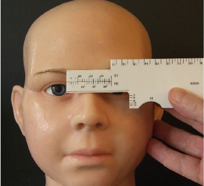
Figure 2 Measuring crest height (3mm) from the bearing surface of the nose to a horizontal intersecting the left lower limbus
After crest height, the next measurements to be taken and marked on the diagram (or slab of acetate if you were making the frame yourself) would be apical radius (figure 3), and distance between rims (DBR) at 10 and 15mm below crest (figures 4 and 5).
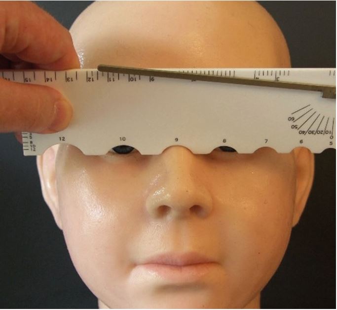
Figure 3: Apical radius (in this case, 9mm)
It is worth noting that the DBR@10 measurement shown in figure 4 is likely to be erroneous. Comparing the ruler’s bearing surface in the figure to the others (see figures 2, 3 and 5), it is at least 2mm higher. This could be because the camera was held at a different height. However, a tripod was used so it must be due to an error in technique. The ruler is not level, being down slightly on the left (patient’s right), but it is also being held higher up the nose. It is sometimes difficult to gauge the position of the crest, but another issue at play here is a ‘sticky’ cursor that is too tight and difficult to move freely. This can usually be alleviated by removing any sharp edges with very fine sandpaper to make measurement easier.
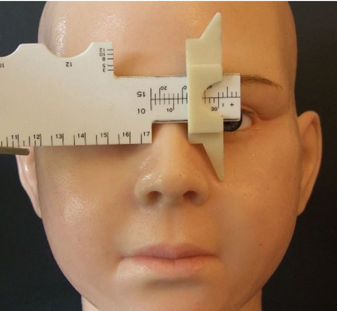
Figure 4: Distance between rims at 10mm below crest or DBR@10 (here showing 17mm)
So it is important to remember that the DBR@10 must be taken holding the facial gauge in the left hand and the DBR@15 using the right hand (as shown in figure 5), and in each case the rule should be angled inwards to replicate an appropriate pantoscopic angle of approximately 10º typically (but may be 0º if the pupil centre is required to be on box centre as is sometimes requested with round eye frames).
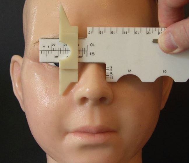
Figure 5: Distance between rims at 15mm below crest or DBR@15 (in this case 23mm)
A lack of familiarity with taking the measurements, viewing the scales on the rule, and a seeming inability to comprehend that ambidexterity might be required, leads to some comical situations in exams. Students frequently place the cursor back to front, the wrong way around, or both, and needlessly lose marks. One day it is hoped that the manufacturer will realise that, if only they would put the bridge projection line on the other side of the cursor, they could avoid the need for the cursor to be removed (and lost) altogether and prevent these errors once and for all.
Perhaps the most unforgivable error is that of ‘funnel nose’ where correct measurements are recorded incorrectly with a wider DBR@10 than the DBR@15. Although noses are occasionally parallel, they are never narrower at the bottom than at the top. With even a modest amount of practice, including drawing out the bridge actual size, students should avoid such errors and investment in a facial gauge pays for itself many times over if even one resit-exam is avoided.
When measuring frames (or perhaps specifying a hand-made frame based on a stock frame, a patient’s previous frame, or a fitting set front), bridge width is an alternative DBR measurement and a useful additional reference point. However, the authors are unaware of any formal means of measuring bridge width on the face, but surmise that positioning the rule 5mm above lower
limbus (facial HCL) using the crest height scale (to align approximately with pupil centre) and then sliding the rule across to use the DBR@10 cursor, would be accurate.
Once these bridge measurements have been obtained and marked, it is time to join the points together to show the initial shape of the bridge (figure 6), which may can then be cut out and tried on the patient if desired to eliminate unnecessary error. It is also a good way for students to practice on each other and family and friends as exam preparation.
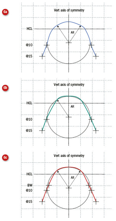
Figure 6: Joining the measurements apical radius (AR, 9mm), bridge width (BW, 17mm) and DBR@10 (19mm) and DBR@15 below (23mm) HCL to show the profile of the bridge from the front. In the cases below, which has used PowerPoint’s ‘curve’ auto-shape function to join the dots, it can be seen that care needs to be taken when using the same measurements to ensure an appropriate width within which to constrain the apical radius. The facial gauge itself can provide this. It is also wise to use as many data points as possible and the addition of bridge width smooths out the computer-generated curve. Most ‘hand-made’ frames utilise CADCAM technology (computer aided design and manufacture) and join the dots using similar algorithms
Rather than use two DBR measurements, an alternative is to use a single DBR or the bridge width measurement and connect to the apical radius using the frontal angle (figure 7).
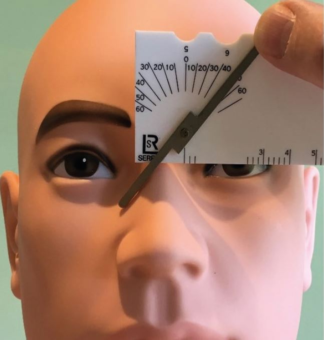
Figure 7: Frontal angle, here 40o, may be a better alternative means of constructing the bridge, especially if the nose has straight sides
Once the frontal shape of the bridge has been determined, it is then necessary to think of the profile of the bridge, that is its shape in three-dimensional space (determined through crest and splay angles), and the future relationship of the rear lens surface with the patient’s eyelashes – namely the bridge projection.
Bridge Projection
Most adult patients have a positive bridge projection, that is the bridge of their nose is further forward than the tips of their eyelashes (figure 8).
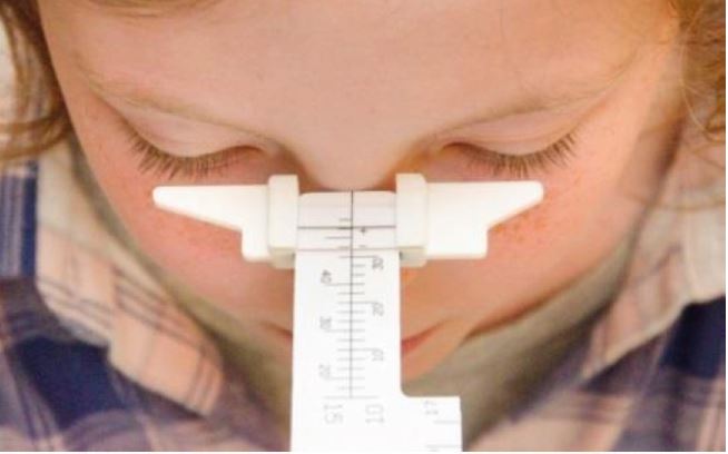
Figure 8: Facial bridge projection
In this case a regular bridge hand-made frame would have the bridge ‘bumped’ to push the lenses back towards the eye so that they fit as close as possible to maximise field of view without touching the lashes (figure 9).
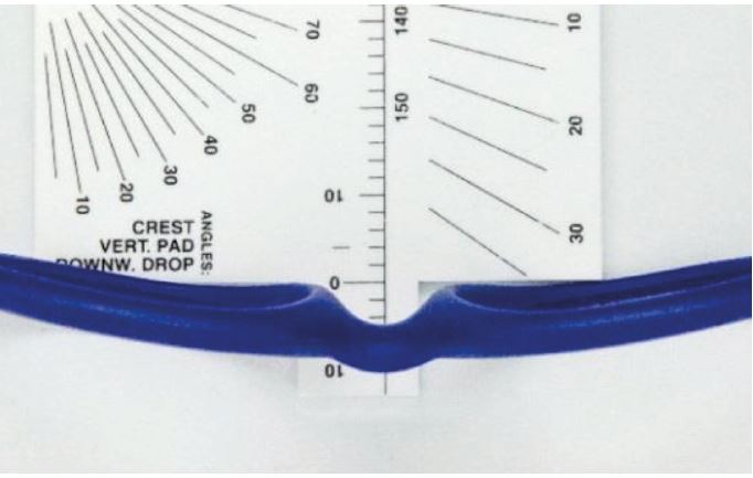
Figure 9: Frame bridge projection
Patients with long, perhaps false, eyelashes or very flat or low bridges will likely have a negative bridge projection. With a regular bridge frame, this means building up the back of the bridge to accommodate the appropriate projection. This is a feature that is seen quite commonly on babies’ frames, but has generally fallen out of favour across the stock frame market.
Negative bridge projections are not uncommon in patients of African and East Asian ethnicity. However, they are easily accommodated with frames with adjustable pads on arms. Most repair workshops will also convert any plastic frame to have adjustable pads on arms if the patient wants a particular acetate style for fashion reasons, or the conversion can easily be done in practice.
Once the acetate slab has been cut to the shape of the front, it is necessary to smooth off the sharp edges and shape the bridge so that it will be comfortable by removing material on the inner edge of the bridge to reflect the crest and splay angles of the nose (figures 10, 11 and 12).
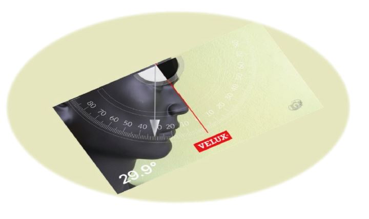
Figure 10 Crest angle, assuming the back plane of the front to be vertical
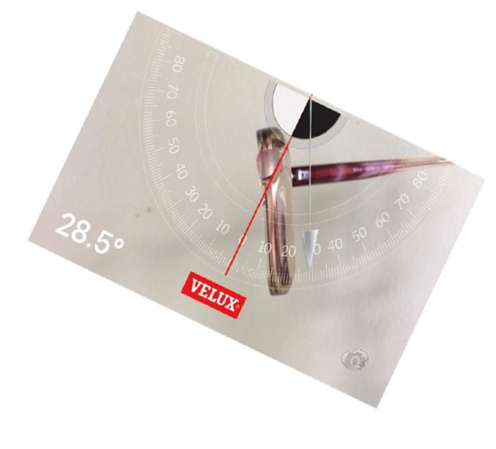
Figure 11 The frame has been cut in half at the bridge to show the angle of crest. It should be noted that the frame is in the ‘as worn’ position with a suitable pantoscopic angle. As the app measures to the vertical plane, the frame angle of crest will be greater by the amount of the pantoscopic angle (here around 35º)
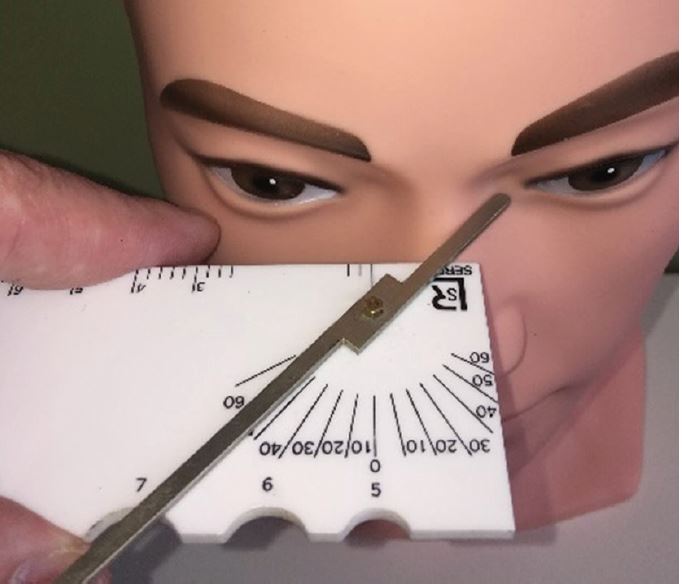
Figure 12: Splay angle (here around 43º)
Crest Angle
The crest angle lies between the back plane of the front and the bearing surface of the nose at the crest in the medial plane. It is shown in figure 10 being measured with an iPhone using an inclinometer app (available from Velux roof windows). This handy free app can be used to measure a variety of angles including pantoscopic tilt.
Splay angle
Splay Angle is only essential on regular bridge frames if the rims are particularly thick and is more often specified on fixed pad / keyhole bridges. It is defined as: the angle between the pad plane and a normal to the back surface of the back plane of the front. This is shown in figure 12.
Lens size and shape
Having ‘joined the dots’ to create the profile of the lower surface of the bridge, it is then necessary to consider the size and shape of the lenses and the overall appearance of the spectacles. If, because of a high prescription, the aim is to have zero decentration, then the right and left vertical centre lines can be marked at this point to coincide the BCD with the patient’s PD. Then a lens shape can be chosen, perhaps based on stock frame dummy lenses or a former, and added to the diagram in the form of horizontal and vertical box dimensions. Care must be taken to select a shape and DBL that will allow for the rim to be sufficiently thick to allow for a groove to accommodate the lens bevel and to be physically strong enough to allow for the rigours of glazing and daily wear. 3mm is normally considered the absolute minimum (figure 13).
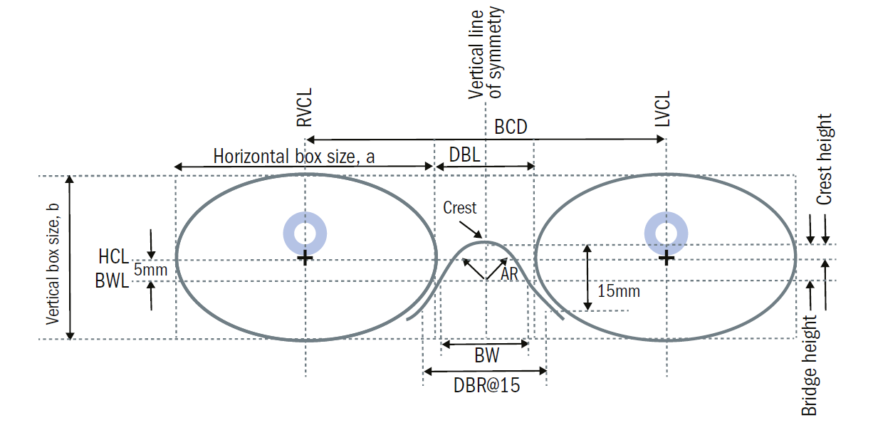
Figure 13: The major reference points of the boxed lens system used when designing a hand-made (or any other) frame: Horizontal Centre Line (HCL); Right and Left Vertical Centre Lines (R/LVCL); Vertical Line of Symmetry; Bridge Width Line (BWL), located 5mm below HCL. Also shown are Apical Radius (AR), Crest Height, Bridge height and width (BW), and DBR@15. Not to scale or pictured measurements
Exceptions that prove the rule
Common scenarios for which hand-made frames are required include the following:
- a very wide, low or splayed bridge
- very wide temple/head width, especially if in combination with a narrow PD
- narrow head/temple width, especially relative to side length
- asymmetry
- very wide PDs
In the second scenario in this list, wide head with narrow PD, it may be impractical to manufacture the frame such that no decentration is required. In this case, mark the PDs on the diagram. The vertical centre line can only be marked after the horizontal lens size has been decided upon.
At this point, the vertical extent of the lenses will also need to be determined. It may be that the patient requires an extra deep frame. For example, if they have a big nose with a high bridge and deep-set eyes, their main concern may be to avoid looking under the bottom rim. Here we need to add depth to the bottom of the lens but will probably not want to add height to the top. When we do this, as is often the case, we need to be aware that this has the effect of moving the HCL of the frame and it will no longer coincide with the facial HCL originally used and, as a result, most measurements will need to be re-calibrated. This probably explains why even the most seasoned of hand-made frame specialists may ask the lab to copy a stock frame with only the measured changes specified. They may even request that the sides from the stock frame are utilised too.
It is difficult, without the use of reference samples, to design the shape, thickness, size and position of the lug (the portion of the front that contains the front half-joint or hinge) that connects to the side. Joint heights are specified from the centre of the joint to the horizontal centre line. The frontal width, measured between the dowel points according to BS3521:Part2:1991 26 115, should be specified as being at least as wide as the patient’s temple width. The joint height should broadly correspond to the height of the patient’s ears.
Because the lug height relative to ear height affects the angle of side, which in turn determines the pantoscopic angle on which the angle of crest depends, a great deal of thought goes into the correct specification of a hand-made regular bridge frame. This applies to the sides as well as the front, though remember the flexibility to adjust sides to a much greater degree than fronts.
Side measurements have already been discussed in this series. However, it is worth noting that, in practical exams, students may be required to measure the front to bend between the lug point and ear point (BS3521: 26 423). This is traditionally taken from a plane through the crest of the bridge to the ear point. The tolerance for front to bend may be as little as 2 or 3mm, yet it is altered by both bridge projection and face-form angle. A negative bridge projection of 4mm would add 4mm to the front to bend, whereas applying a wrap angle of 5º would reduce it by 5 or 6mm, depending on frame size, all of which needs to be accounted for.
Conclusion
Patients with narrow PDs, high prescriptions and wide heads may well be more easily catered for by specifying a bespoke rimless than a handmade acetate frame. By matching the lens shape to the prescription, cylinders of up to 6.00DC and spheres as high as -17.00DS and +10.00DS have produced excellent results in the authors’ experience. Similarly, patients with high bridges who look under the bottom rim of stock frames might more easily be dispensed with a supra or rimless mount, with an increased lens depth to satisfy their optical needs.
However, given the ongoing fashion for plastic frames, opticians should be prepared to work with patients to satisfy not only their optical and comfort needs, but also their aesthetic requirements. The current revolution in 3D scanning, additive manufacturing technologies such as 3D printing, and computer aided design and manufacture that facilitates bespoke frame production to traditional measurement specifications, are all tools that will help opticians to satisfy their patients’ needs. Whether ordering traditional hand-made regular bridge frames, refining computer-generated measurement, or simply sitting a professional qualifying examination, a core understanding of the system of measurement and how to take and adapt relevant measurements is core competency for all practitioners involved in ophthalmic dispensing.
Peter Black MBA FBDO FEAOO is senior lecturer in ophthalmic dispensing at the University of Central Lancashire, Preston, and is a practical examiner, practice assessor, exam script marker, and past president of the Association of British Dispensing Opticians.
Tina Arbon Black BSc (Hons) FBDO CL is director of accredited CET provider Orbita Black Limited, an ABDO practical examiner, practice assessor and exam script marker, and a distance learning tutor for ABDO College.
Bibliography:
The following publications have been used in the compilation of this article:
- BS 3521:Part2:1991 Terms relating to ophthalmic optics and spectacle frames. Part 2. Glossary of terms relating to spectacle frames.
- BS EN ISO 7998:2005 Ophthalmic Optics – Spectacle Frames – Lists of equivalent terms and vocabulary
- BS EN ISO 8624:2011+A1:2015 Ophthalmic Optics – Spectacle Frames – Measuring system and terminology
- Fairbanks Facial Gauge – Instructions for use
- Practical Optical Dispensing, 3rd Edition; David Wilson, Steven Daras. OTEN. 2014.