The previous article discussed best form lens designs that seek to reduce or eliminate the major monochromatic aberrations oblique astigmatism, curvature of field and to a lesser extent distortion. It was determined that lenses that utilise spherical curves cannot be made in best form in hyperopic prescriptions over +7.00DS to +9.00DS regardless of the refractive index. Additionally, complex lenses over +/-10.00DS mark the point at which lens thickness and weight become so problematic, and comfort often becomes such an issue, that a patient may feel this takes priority over optical or visual considerations. Lens designers have therefore been compelled to look away from standard spherical surfaces and full aperture designs in order to meet the needs of patients.
Monochromatic aberrations
It is worth briefly recapping that 3 of the 5 monochromatic Seidel aberrations are of main concern in spectacle lens design;
- Distortion
- Curvature of field
- Oblique astigmatism
Distortion is caused by peripheral areas of a lens having different thickness to central parts and therefore a different shape factor causing greater spectacle magnification in plus powered lenses and minification in minus powered lenses towards the periphery (figure 1). Best form lenses with spherical surfaces do not substantially reduce distortion.
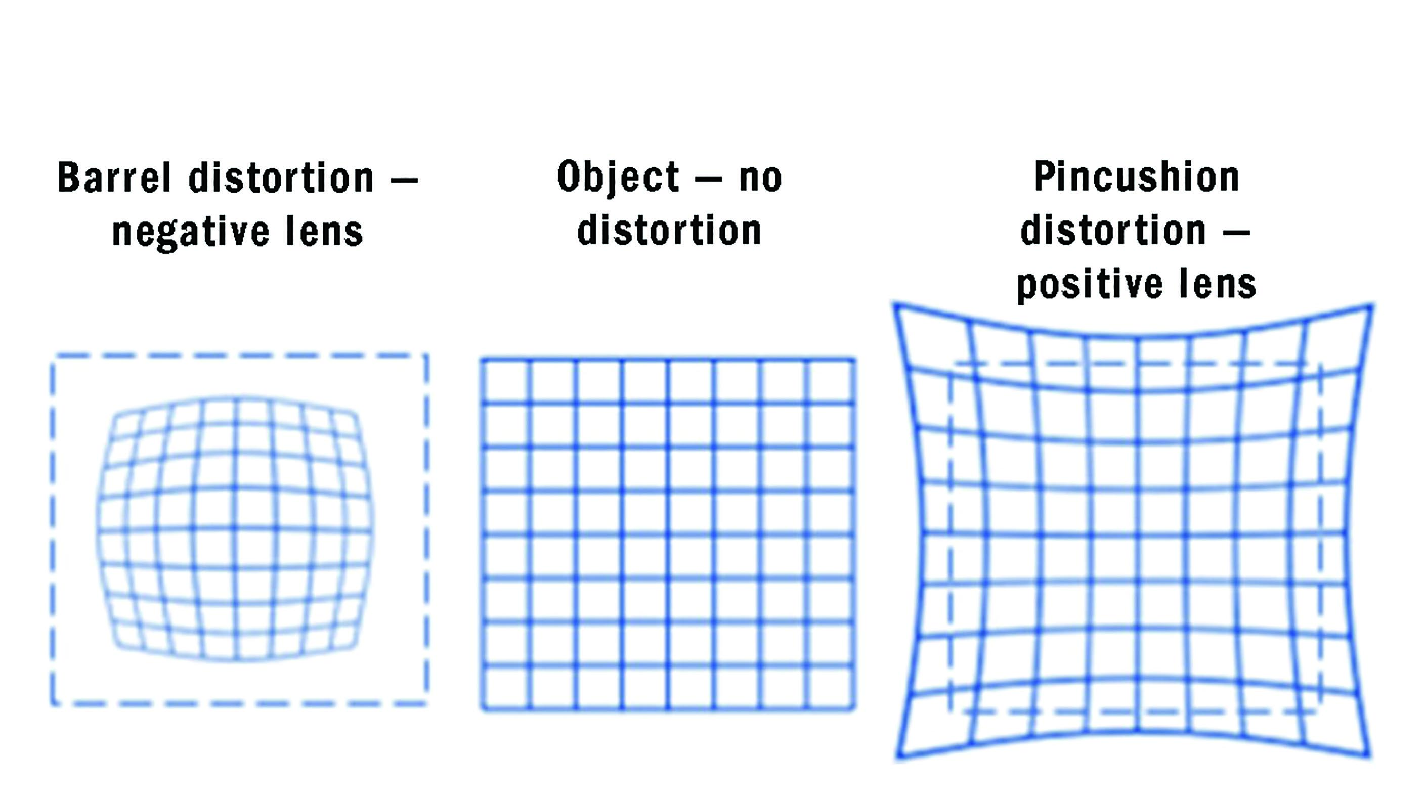 Figure 1: Distortion
Oblique astigmatism
When light is incident obliquely on a lens surface it has a different angle of incidence in the tangential (radial) plane compared to the sagittal (meridional) plane. Depending on the form of the lens aberrational astigmatism is often induced even in a lens of spherical power (figure 2). Lens designers have a choice where to place the image shells relative to the far point sphere. Percival form lenses have the circle of least confusion on the far point sphere. Minimum tangential error (MTE) designs place the tangential focus on the far point sphere however with accommodation a patient may be able to bring the circle of least confusion or the sagittal focus to the far point sphere.
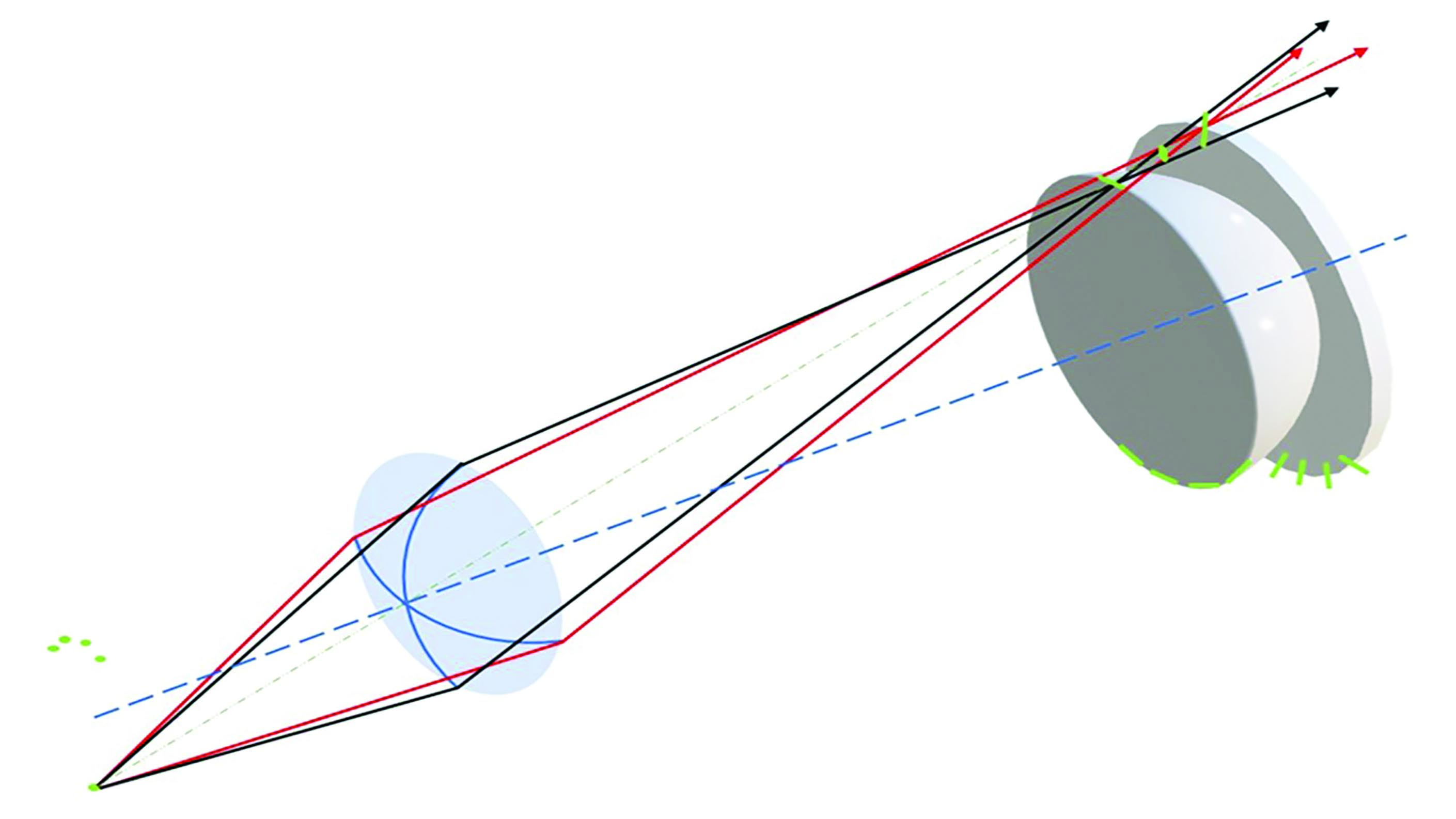 Figure 2: Oblique astigmatism
Lens designers can select base curves to completely eliminate oblique astigmatism – so called point focal lenses - however when oblique astigmatism is completely eliminated oblique images do not lie on the far point sphere and some power error remains.
Power error (Curvature of field)
Power error occurs when sagittal rays and tangential rays from a given off axis object are focussed to the same point, but that point does not lie on the far point sphere and instead lies on an image shell known as the Petzval surface (figure 3)
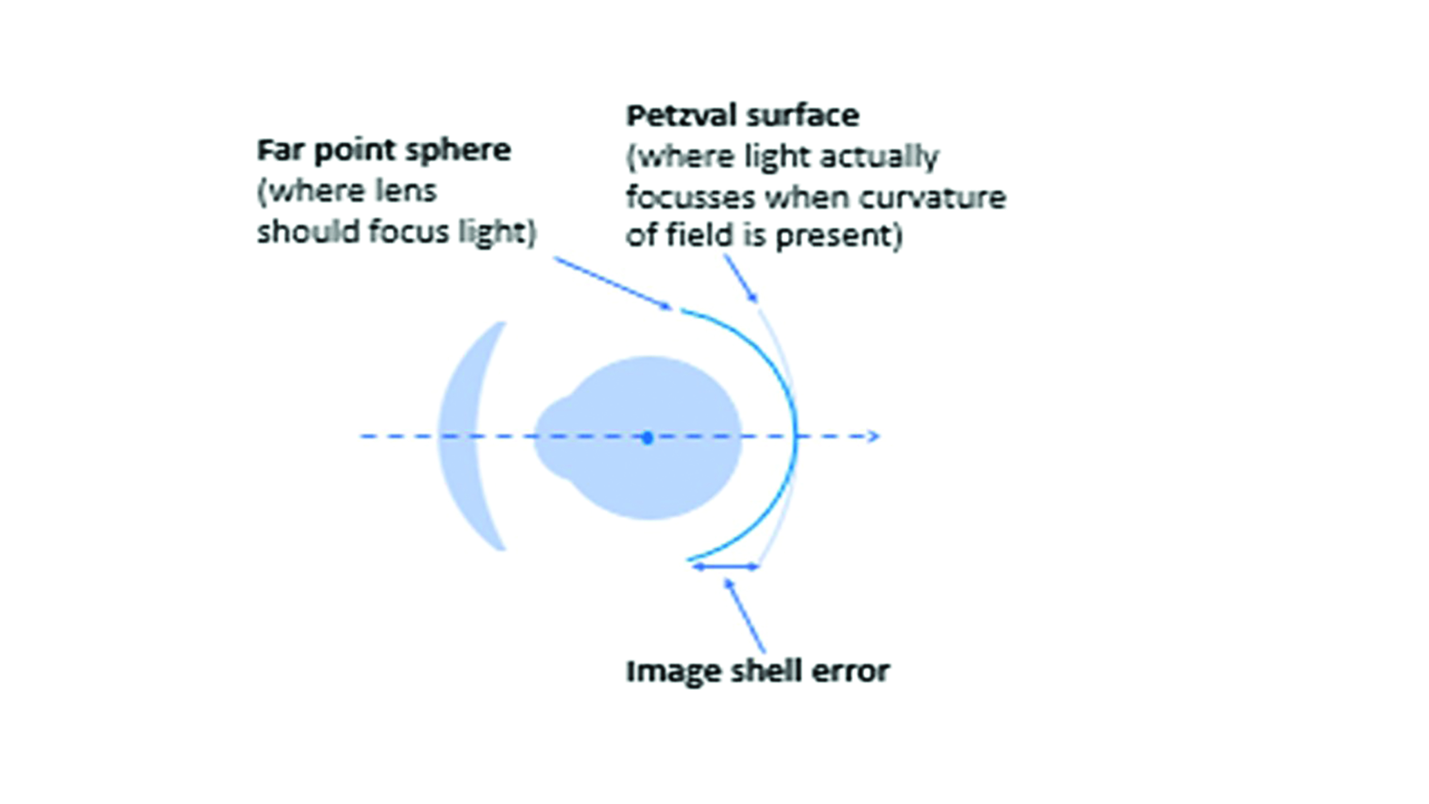 Figure 3: Power error
Field diagrams allow visualisation of the relative amounts of power error and oblique astigmatism simultaneously for a range of angles of eye rotation without complex three-dimensional
diagrams.
A theoretically perfect lens would have no power error and a clear image would be focussed on the far point sphere at all directions of gaze (figure 4). Unfortunately, no such spectacle lens exists.
 Figure 4: A theoretically perfect +4.00DS lens field diagram
The very considerable aberrations that occur with flat form lenses make it imperative that during refraction trial frames/phoropters are fitted with the plane of the front perfectly vertical and the centre of the trial lens, which is flat form, perfectly aligned with the pupil centre such that the pantoscopic angle is zero. Figure 5 shows the field diagram for a +4.00DS trial lens made in plano-convex form. It can be seen that at 20˚ eccentricity (eg 10˚ tilt plus OC 5mm up due to low sitting trial frame) the sagittal power is around +4.25DS and the tangential power +4.75DS. In other words, in the primary position of gaze, the patient is experiencing +4.25/+0.50 x 180 when the optometrist would prescribe +4.00DS.
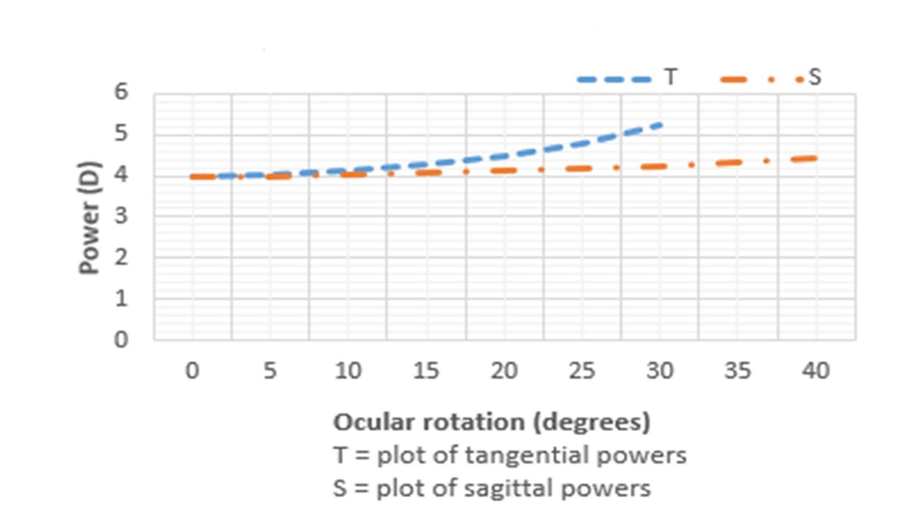 Figure 5: A field diagram for a +4.00DS trial lens
Best form lenses
Lenses designed to reduce or eliminate the above aberrations and provide the highest standard of off axis visual acuity are known as best form. The form of lens required for a given back vertex power can be determined from Tscherning’s ellipses, there being different ellipses for each lens design philosophy, refractive index, working distance and centre of rotation distance (which is normally assumed to be 27mm).
It should be noted that all best form lenses are more bulbous and therefore cosmetically inferior to their flat form cousins and also that traditional best form lenses utilising spherical (circular) curves are only available in prescriptions from around -35.00DS to around +7.00DS in point focal form, or +9.00DS in minimum T-error form (figure 6).
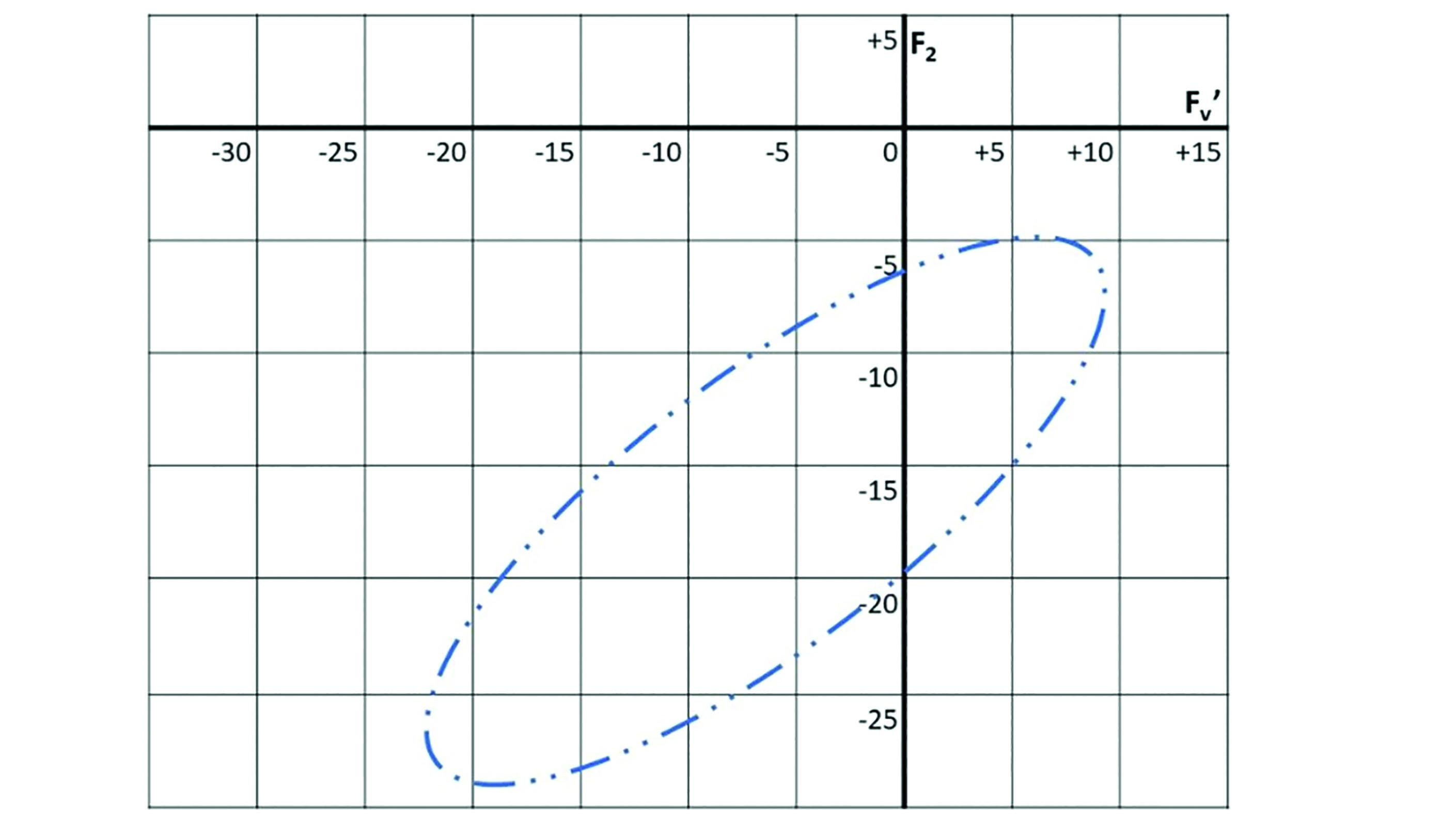 Figure 6: Tscherning’s ellipse for distance vision minimum T-error lenses, n=1.50
Although this prescription range caters for over 99% of myopes, it leaves a significant proportion of hyperopes, and especially aphakic patients, without a best form lens option. As cataract surgery became more common place the requirement for better lens options for this group of patients, in terms of thickness, weight and optical performance, became a priority for lens designers.
Lenticulars
Above a certain lens diameter, or frame size, full aperture lenses become impractical, or even impossible to provide. The size of a lens is limited strictly by the radius of curvature of its surfaces and also the thickness that can be practically accommodated before the eye by a frame. Over a certain size, depending upon the prescription and the refractive index of the material an aperture smaller than that of the boxed lens dimensions of the frame will be required. Such reduced aperture lenses are termed lenticulars.
Minus lenticulars
Consider a -30.00DS lens made in 1.5 refractive index in plano-concave form;
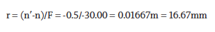
The absolute largest diameter of the lens, assuming a semi-circular, or rather hemi-spherical, surface, would be 33.33mm with an edge thickness of 16.67mm plus any centre substance, making it clearly impractical in terms of fitting to a frame. Even in 1.7 index the maximum diameter would be only 46.67mm when the lens would be nearly an inch thick. Reduced aperture lenses are therefore the only option and with a high minus power there are many lenticular designs (figure 7). They also incorporate best form optics with front surface powers usually close to plano, or of concave form in the highest powers.
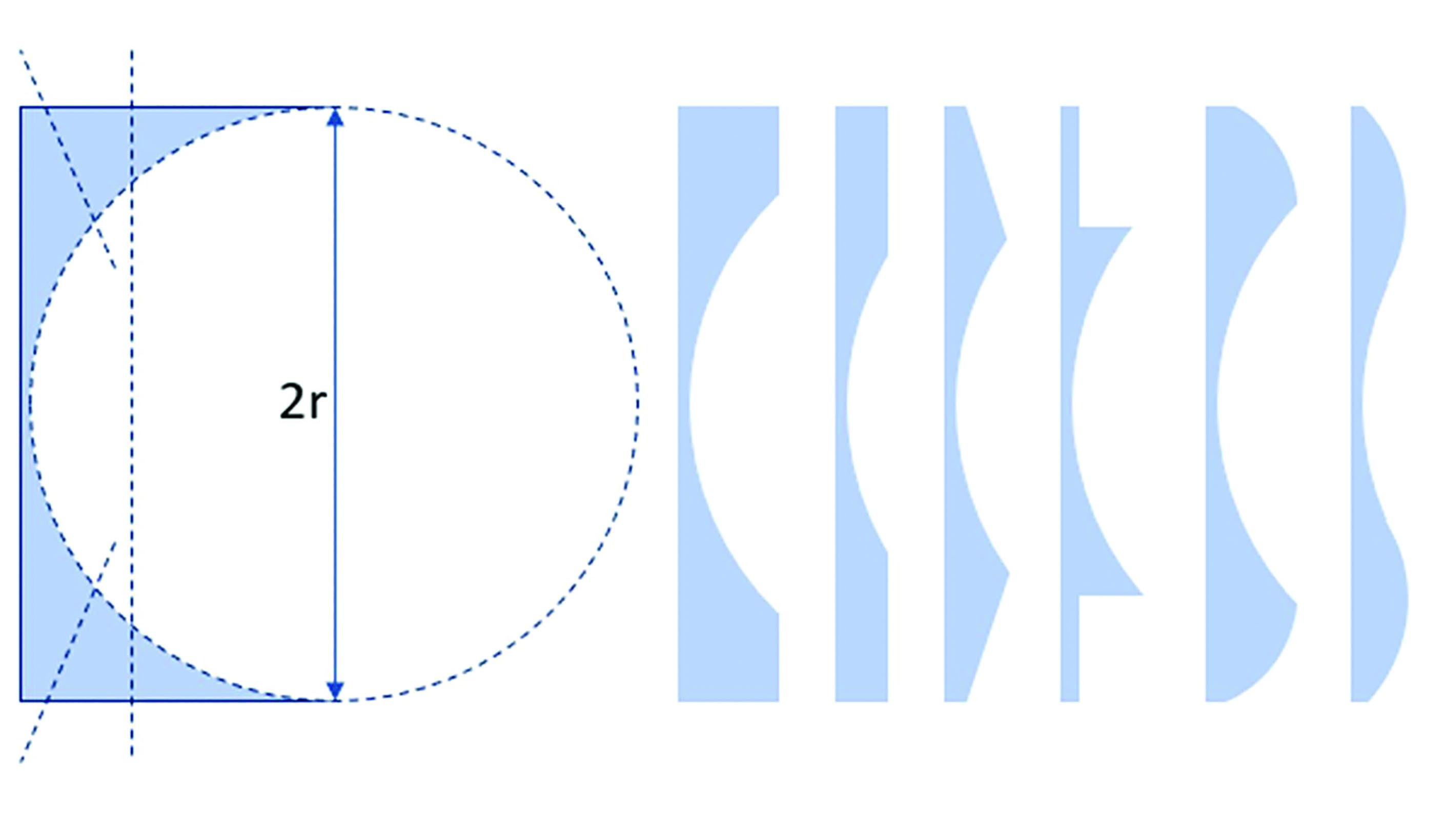 Figure 7: Concave lenticular designs
With a plano front surface it is possible to produce the concave back surface from a flat plate of glass/plastic, thereby giving a plano margin with the same thickness as the edge of the optical portion (or bowl) of the lens. The thinner the lens, the smaller will be the optical portion. The margin could potentially be further shaped to remove unnecessary material and produce a plano, flat bevelled or even a convex margin to reduce the weight of the lens. The lowest weight concave lenticulars have a thin plano carrier, it is possible for the optical portion of the lens to be circular or specially shaped to match the rim of the frame. This is called a profile lenticular. Those with a blended margin between the optical and non-optical areas of the lens (such as Myodisc and Rodenstock Lentilux designs) offer the best compromise between optical performance, weight and cosmetic appearance.
Positive lenticulars
A minus lenticular lens can be manufactured relatively easily from a standard unfinished lens blank (subject to tool availability) with the surfacing process not only providing best form optics but also leaving a margin to enable the lens to be fitted to a frame. The same cannot be said of a high plus powered lens where the edge of the lens blank is removed in the process of surfacing and best form optics with spherical curves is not possible.
Lenticular lenses for the correction of high hyperopia or aphakia come in a more limited range of designs compared to their myopic counterparts. However, the necessity for moulding the front surface of the lens has enabled manufacturers to experiment with different non-spherical curves and also add bifocals and progressive power lenses to their ranges which is of great importance given the absence of accommodation in aphakic patients.
Early ‘cataract lenses’ involved bonding a small positive powered spherical lens, or button, to a plano carrier lens. Most modern lenticulars have a concave back surface into which any cylinder required is also incorporated. Figure 8 shows five lenses with the same front vertex curvature (in plano-convex form for illustration purposes), from left to right as follows;
- the full aperture lens at maximum diameter
- a button lenticular with spherical button
- a button lenticular with prolate ellipsoid button
- a 4-drop design
- a blended aspheric lenticular.
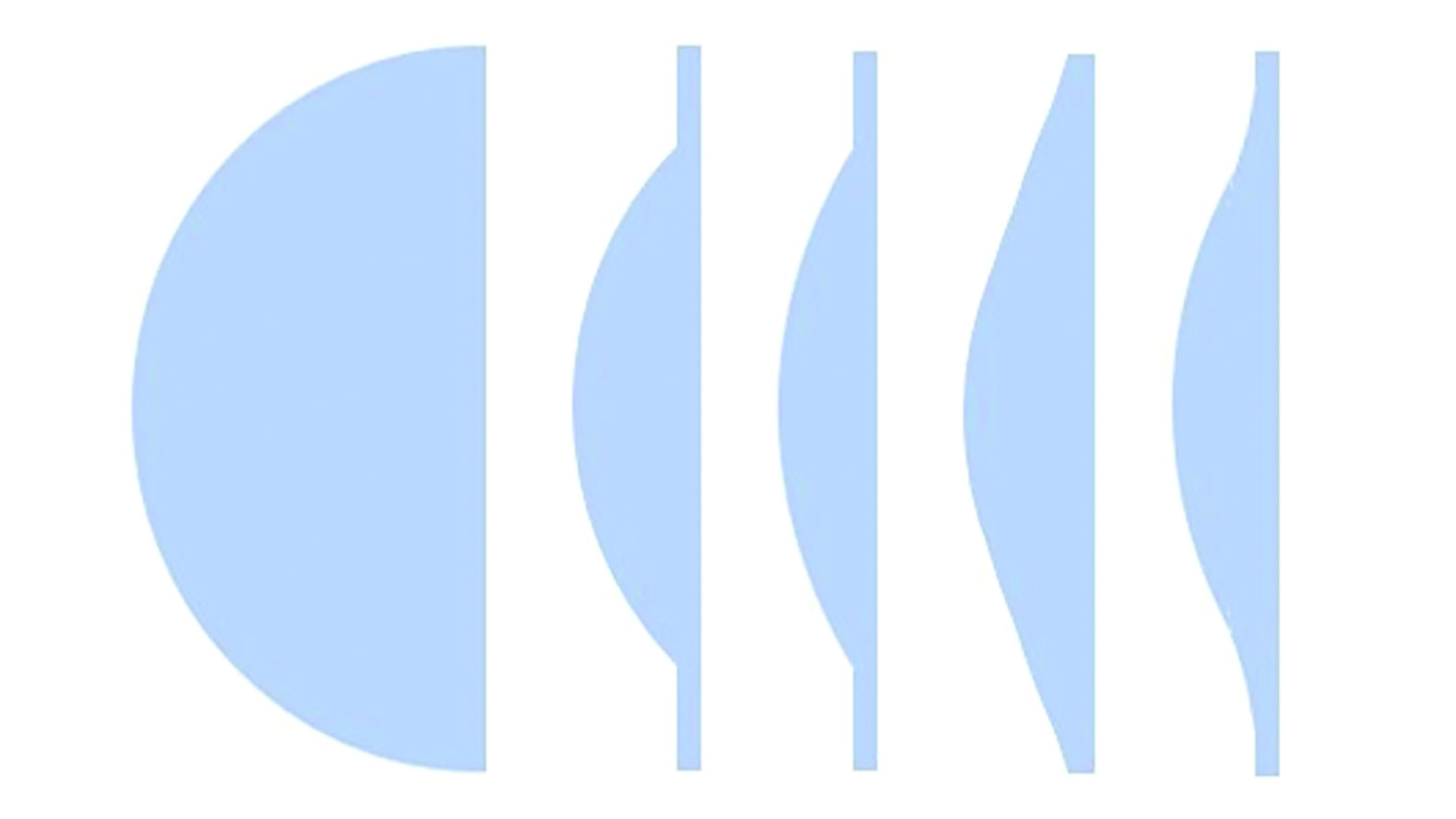 Figure 8: Positive lenticular forms
Aphakic patients present numerous challenges, not the least of which is a total lack of accommodation which makes any ‘under-plussing’ of the distance prescription very evident and an accurate working distance for the near vision prescription vital. The lack of best form lens options creates substantial off-axis aberrations and near vision effectivity error which, between them, can cause a difference of 2.00DS or more from that which has been prescribed.
The most common reason for the distance prescription to be underpowered is likely a failure to properly compensate for a frame that fits at a closer vertex distance than the trial lens. Even though it will require an even more plus lens, that is thicker and heavier, it is vital that the frame fits as close as possible without touching the lashes in order to maximise field of view.
Field of view in an aphakic patient is a public health concern since it is potentially so restricted that patients who drive could become a danger to other road users and themselves.
The restriction of the field of view in any lens can easily be determined by calculating the field of view through an aperture of the same size (eg an empty frame or plano lens), that is the apparent field of view, and comparing it to the real field of view once prismatic effect at the edge of the lens has been taken into account. Figure 9 shows the field of view with a lenticular button diameter, 2y, and centre of rotation distance, x, where the apparent field of view is 2θ and the real field of view is 2(θ-P) and P=cF in Δ and 100 tanP in degrees.
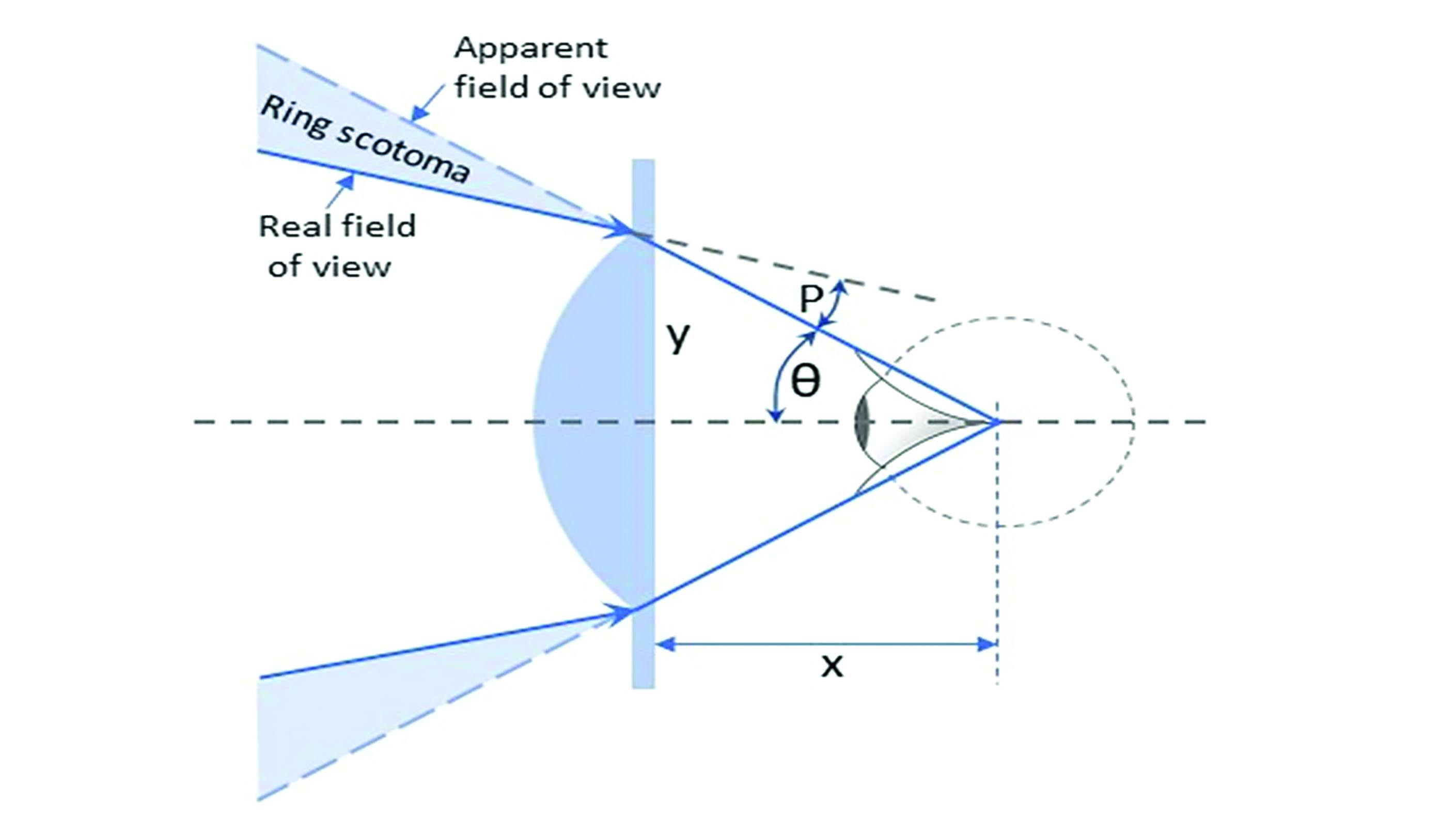 Figure 9: Field of view in a positive lenticular. The shaded triangles show the blind area (ring scotoma) that encircles the field of clear vision and gives rise to the Jack-in-a-box effect.
Take a 40mm button lenticular, +12.00DS, and centre of rotation distance, c = 27mm. At the edge of the button P=cF = 2x12.00 = 24Δ 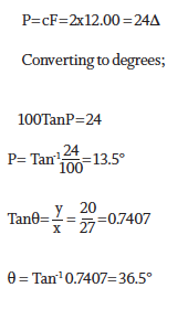
You get;
- The apparent field of view is 73°
- The real field of view = 2(36.5-13.5) = 46°
Straightforward calculation reveals that, at a distance of 10m, the linear extent of the ring scotoma is some 1.9m to both the left and right of a central 8.5m horizontal field of view. This is easily enough to contain a parent, toddler and baby in a pushchair waiting to cross at the zebra crossing. Perhaps more sobering is the fact that reducing the back vertex distance from a notional 12mm (and corresponding centre of rotation distance of 27mm) by just 4mm would increase the real field of view by 9° or nearly 20%.
High hyperopes and congenital aphakes are well versed in turning their heads to extend their field of view and counteract the Jack-in-a-box effect as objects suddenly appear as if from nowhere in their peripheral vision. It is rare these days, thanks to advances in cataract surgery and intraocular lens implants, to see a patient who is aphakic due to surgery. Nevertheless it would seem prudent to do whatever we can to maximise field of view, fitting the lens as closely as possible without touching the eyelashes, and employing a design that does not suffer from ring scotoma and is easier therefore to adapt to.
It was found that by gradually stepping down the curve of the lens surface, using standard spherical tools, a 4-drop lens design (as illustrated in figure 10) would increase field of view, without significant reduction in visual performance since full aperture lenses suffered so many aberrations. The next phase in lens development was to blend these surfaces during polishing such that the power reduced steadily towards the periphery. Such blended lenticulars were the first use of aspheric surfaces in spectacle lenses.
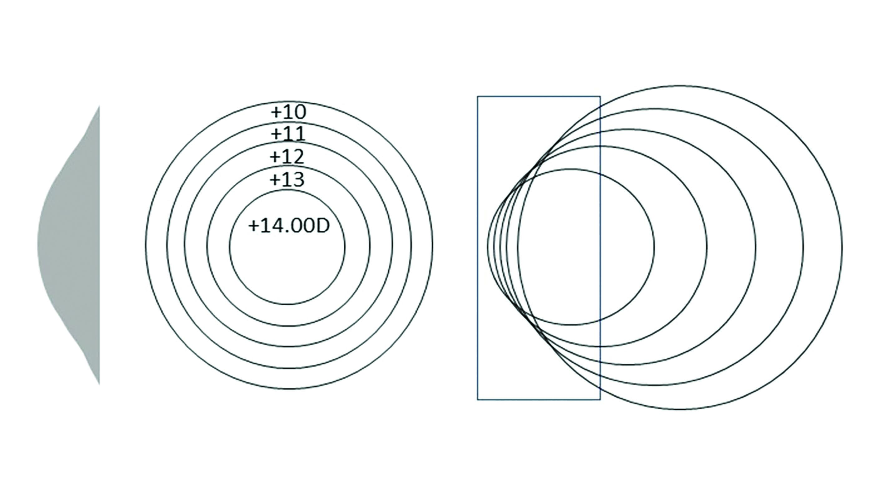 Figure 10: Principle of the 4-drop lens
Aspheric lenses
Aspheric literally means ‘not spherical’. As such toric lenses employing circular curves could technically be deemed aspheric however they are not included within the term because the curves of a toroidal surface are circular in each meridian. Lenses that do not employ these circular curves are said to be aspheric and include both single vision and progressive power lenses.
A change in curvature is noticed over the lens surface, rather than constant curvature like a spherical surface, and in single vision lenses the change is the same in all directions or meridians of the lens surface. Asphericity is achieved by flattening the periphery of the front surface in plus lens and by steepening the periphery of the front surface in minus lens and/or by flattening the periphery of the back surface to reduce the edge thickness.
The principle use of aspheric lens design is the reduction or elimination of optical aberrations produced when looking through an ophthalmic lens obliquely. Although beneficial to almost all patients whatever their prescription, aspherics are the only best form option for patients with moderate to high hyperopia who therefore experience the most benefit in optical terms.
Blended aspheric lenticulars
The principal benefits of aspheric surfaces in lenticulars are full peripheral field of view, improved off axis performance, and better cosmetic appearance. The blending of the power towards the edge of an aphakic lens means that there is no restriction in field of view (figure 11) and, since our peripheral vision is blurred anyway when the eye is in the primary position and responds mainly to movement, it would be of little concern that the prescription is weaker at that point. If the patient chooses to look away from the optical centre this would be of more concern. However, as it happens, blended aspherics dramatically improve off axis performance at least for distance vision as can be seen in figures 12 and 13 which compare the field diagrams for both +12.00DS spherical and aspheric designs.
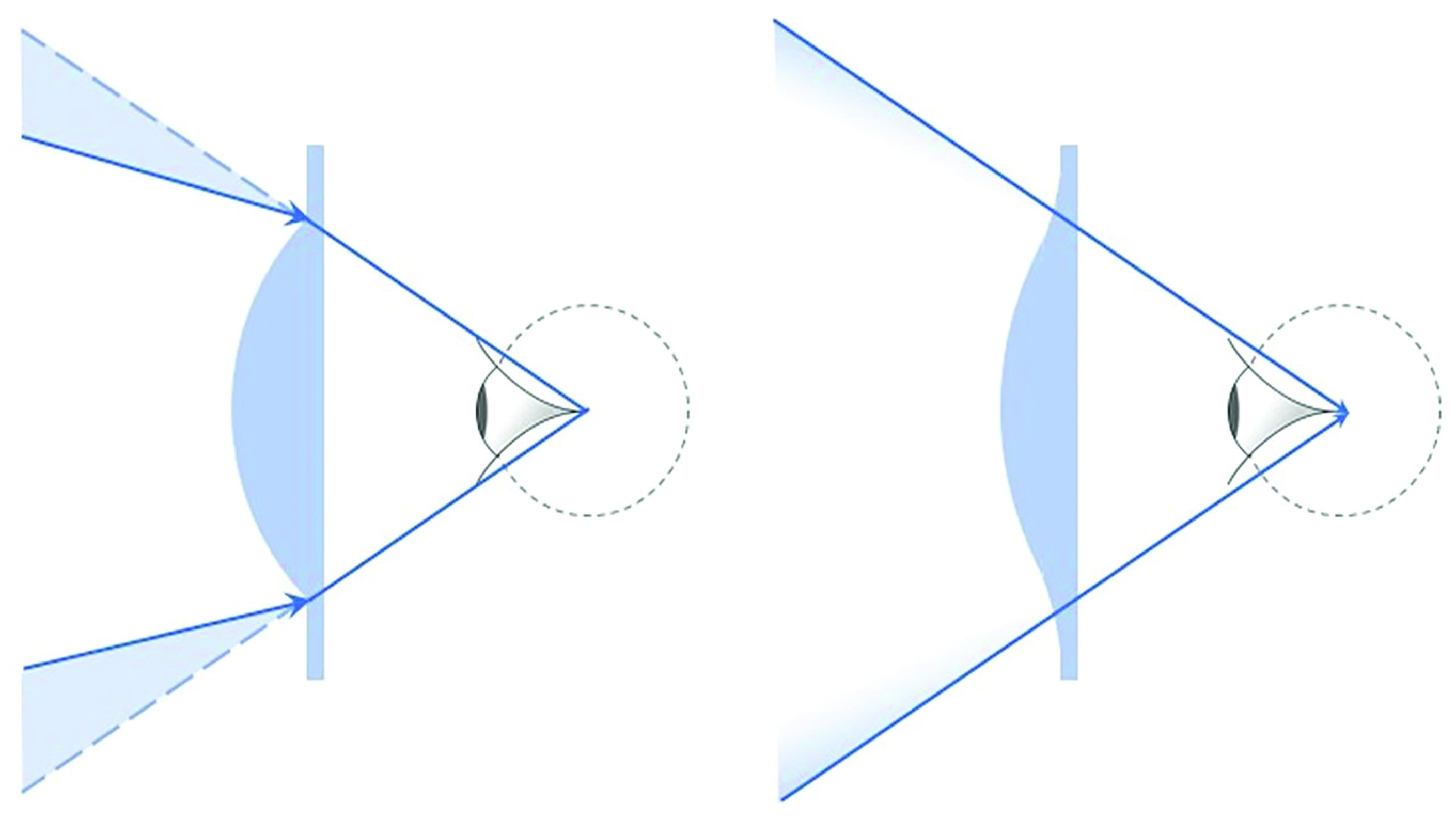 Figure 11: Comparison of field of view in button and blended aspheric lenticulars
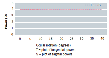 Figure 12: Field diagram for a +12.00DS spherical lens
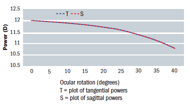 Figure 13: Field diagram for a +12.00DS ellipsoid surface lens
Conic Sections
Aspheric surfaces are achieved by rotating a conic section (a plane through a right cone, which is one whose principle axis is at right angles to its base) about an axis of symmetry. Figure 14 shows the principle conic sections, namely;
- Circle; a section parallel to the base and used in spherical best form lenses
- Parabola; a section parallel to the side of the cone
- Ellipse; a section in between circle and parabola that does not intersect the base
- Hyperbola; a plane that intersects the base at a steeper angle than the side of the cone. Strictly, a hyperbola will also intersect the upper base surface (or ceiling) of a double cone.
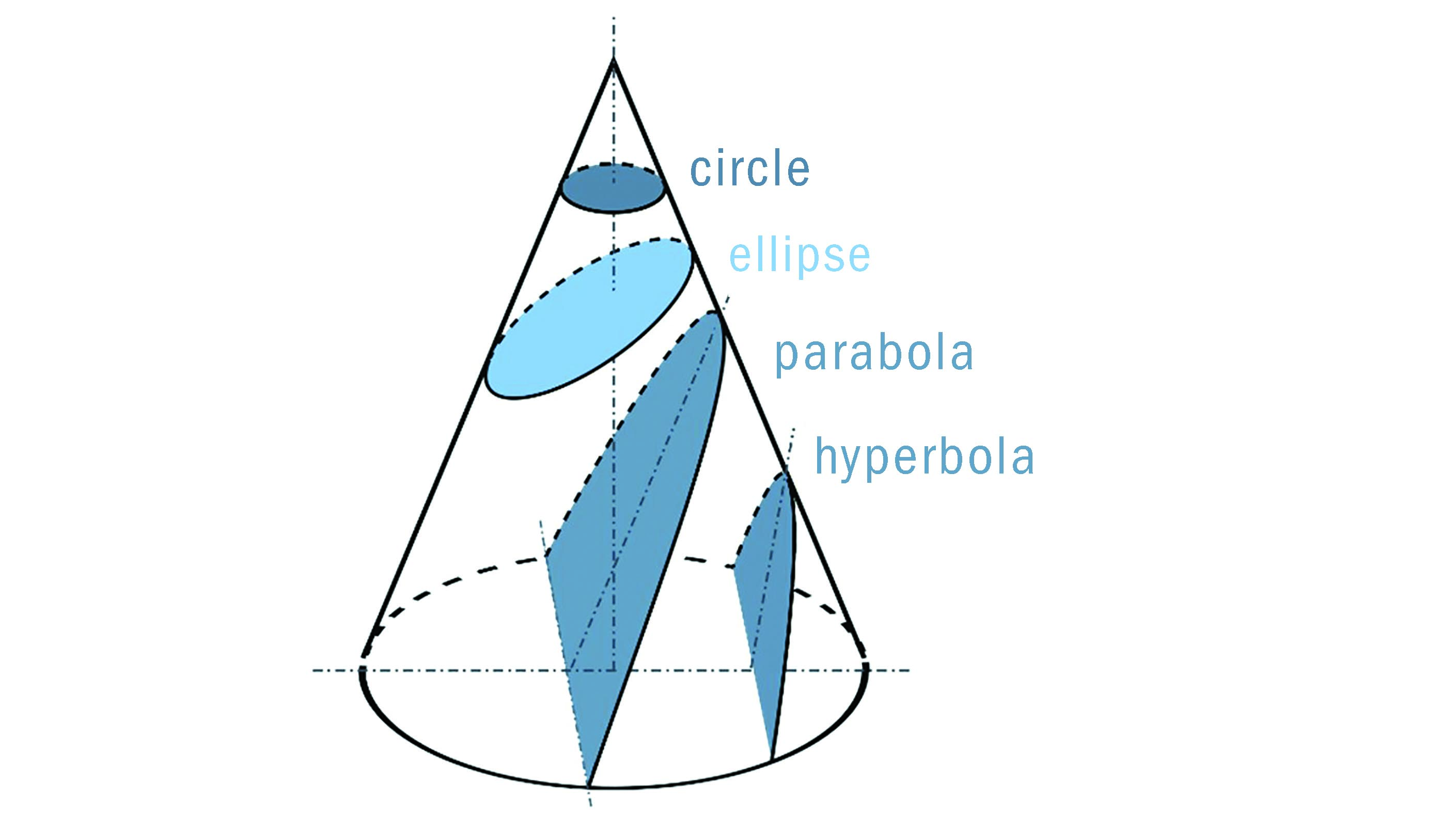 Figure 14: Conic sections
Figure 15 shows the formation of aspheric surfaces using ellipsoid curves. An ellipse can be rotated about its minor or major axis to produce prolate and oblate ellipsoid spheroids respectively. Most aspheric surfaces are prolate, that is they flatten towards the periphery, as found on the front surface of positive lenses and the back surface of minus lenses. Bi-aspheric lenses, especially in minus power incorporate an oblate surface to reduce edge thickness.
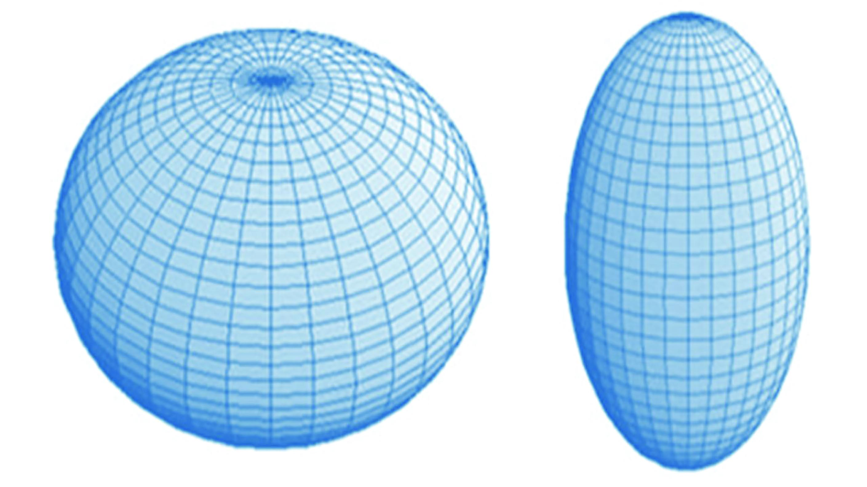 Figure 15: Oblate (left) and prolate (right) spheroids formed by rotating an ellipse about its minor and major axis respectively
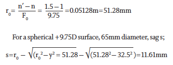
The Sag of an Aspheric Surface
At the pole or vertex, an aspheric surface is spherical and gradually flattens towards its periphery. Figure 16 shows how a prolate aspheric surface has a lower sag than a spherical surface of the same power. However, it is worth noting that curves with the same vertex curvature are not hugely different and the sag of an aspheric curve may only be 10% less than its spherical equivalent. The real saving in terms of sag comes from the fact that an aspheric design can utilise a much lower surface power than a best form equivalent. 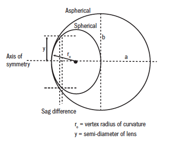 Figure 16: The sag difference between spherical and aspheric surfaces
Referring to figure 16, at the vertex;
 For a spherical surface, sag (s) is as follows;
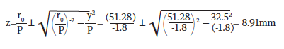
 For an aspherical surface, sag (z) is as follows;
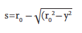
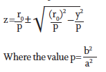 Figure 17 shows p for the family of conic sections. It is used to calculate the sag of an aspheric surface z. It should be recognised that if p=1, the formula for z will become the same as the standard sag formula since the curves are circular, a circle being a special case of an ellipse.
 Figure 17: p values for conic sections used in sag determination
By employing conicoid curves, aspheric lenses have imaging properties very close to point focal (figure 18) with the added benefit of a much flatter lens which is also thinner and lighter. Aspheric lenses are also corrected to a much greater extent for distortion (figure 19) whether in plus or minus prescriptions and suffer much less spectacle magnification improving the appearance of the patient’s eyes to the observer.
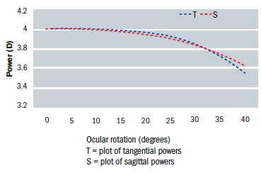 Figure 18: Field diagram for a +4.00DS aspheric lens
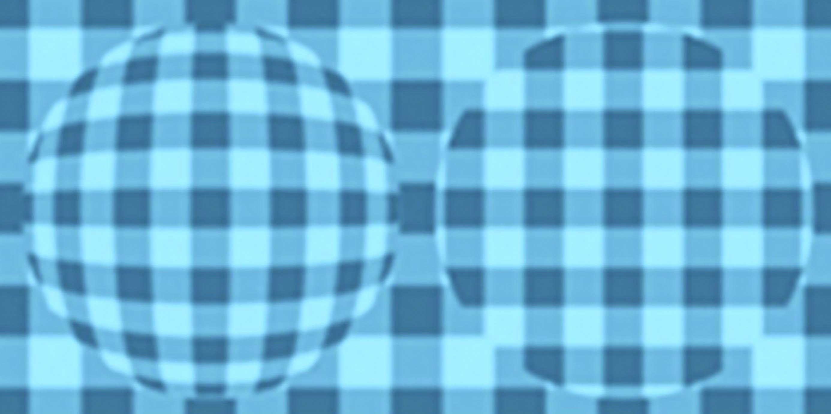 Figure 19: Distortion in -6.00DS spherical lens n=1.50 (left) and aspheric n=1.70 (right)
It is useful to compare curves of the same power, and also lenses of the same power, to gain an idea of the difference choosing an aspheric form makes. It may be recalled from the previous article (see also Table.1) that a point focal lens, Fv′ +4.00DS has a front surface power of +9.75D
At the vertex;
For an aspherical +9.75D surface, 65mm diameter, p=-1.8, sag z;
While this is a saving of over 20%, the real benefit is due to the fact that an aspheric lens actually only requires a front surface power of +5.50DS as can be seen in table 1.
At the vertex;
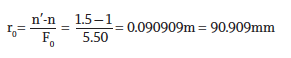
For an aspherical +5.50D surface, 65mm diameter, p=-1.8, sag z;
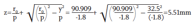
The surface is some 53% flatter and, if we allow 1.5mm for edge thickness, has a plate thickness (a measure of how bulbous the lens is) some 46% thinner than the point focal equivalent. Remembering that this is a standard lens material and further savings can be achieved by increasing the refractive index, it can be appreciated that patients who have had standard spherical lenses can experience stunning improvements with aspheric lenses. This is especially so in moderate to high plus prescriptions, but also in higher minus powers too.
It is useful to compare the field diagrams for different lenses side by side. Figure 20 shows field diagrams for five different forms of a +4.00DS lens. The power in dioptres is plotted horizontally against the ocular rotation in degrees on the vertical axis. Note that the scale for the left hand image is at a fifth that of the other four lenses. Table 1 compares the front surface power for these lenses and also the approximate prescription experienced by the patient at 30˚ ocular rotation.
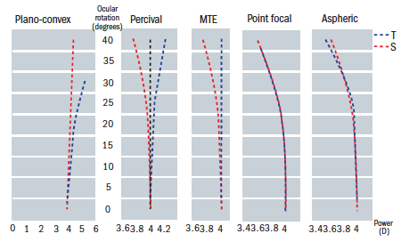 Figure 20: Field plots for five forms of a +4.00DS lens
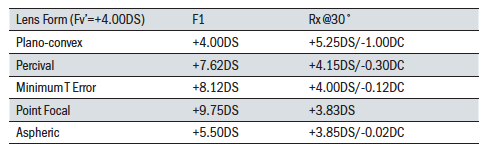 Table 1: Comparison of front surface power and off axis performance for a +4.00DS lens in 5 forms
Dispensing requirements
Aspheric lenses place greater demands upon the optician if the benefits to the patient are to be truly realised. Manufacturing tolerances are unforgiving if the lenses are to live up to expectations. For example, the surfacing lab must ensure the correct base curve is used. Base curves change for almost every prescription, so there are many more options required than for spherical lenses.
The power of an aspheric lens must be checked with the optical centre exactly aligned on the focimeter and the target perfectly central. Moving away from the geometric centre of an aspheric surface, the prescription alters in line with the way the lens surface changes power. Since the curvature of an aspheric surface varies from the centre to the periphery, a normal lens measure cannot determine the front curve value or vertex curvature of an aspheric lens accurately.
The power change along the radial/tangential direction is about 3 times as great as the change in the sagittal or circumferential direction. This inherent astigmatism away from the optical centre is used to balance the oblique astigmatism caused by gazing obliquely through the lens. With most aspheric surfaces in ophthalmic lenses the curvature extending tangentially/radially in all directions from the optical centre changes progressively and the curvature in the opposite sagittal/circumferential meridian also changes progressively but at a much lower rate.
Because of the surface astigmatism towards the periphery it is imperative that the geometric centre of the aspheric lens is aligned with the visual axis and the centre of rotation condition adhered to. This accurate centring of the pole or vertex of the aspheric surface(s) suggests a problem with prescribed prism. Prism cannot be achieved by decentration with any aspheric lens. Prism can be worked but may negate some of the optical performance of the lens design and it is best to consult the individual manufacturer.
The Centre of Rotation Condition
In order to avoid introducing or reintroducing unwanted oblique aberrations, the centre of rotation condition must be observed. At the point where the visual axis intersects the optical centre (back vertex) of the lens and pole of the aspheric surface(s), it must coincide with the optical axis. Monocular interpupillary distances are obligatory for all powers and the face form angle should be close to zero. Heights should be measured to pupil centre and reduced by 1mm for every 2˚ of pantoscopic angle. The pantoscopic angle should be measured every time. Excessive tilt (of over 10˚) should be avoided and a new frame selected if at all possible. If this is not possible, or when a wrap angle of more than a few degrees is required, then a personalised aspheric should be dispensed with surface powers compensated to address the patient’s frame or personal requirements.
Many manufacturers, incorporating state of the art freeform designs, are now able to produce lenses individual to the patient’s requirements including the base curve of the frame, wrap angle and as-worn tilt, and compensating the surface and vertex powers to reduce aberrations. Where this technology is not employed, then the centre of rotation condition is key to avoiding non-tolerance cases.
Figure 21 shows a lens with zero pantoscopic tilt and optical centre (OC) on pupil centre as would occur in during refraction. Figure 22 shows a lens that is tilted in the frame, where the OC has been measured to coincide with pupil centre. This is a common dispensing error. Note that the optical axis does not coincide with the visual axis in any direction of gaze. This is the so-called ‘as-worn’ pantoscopic angle as defined in BS EN ISO 13666:2012. 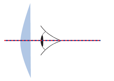 Figure 21: Lens with zero pantoscopic tilt
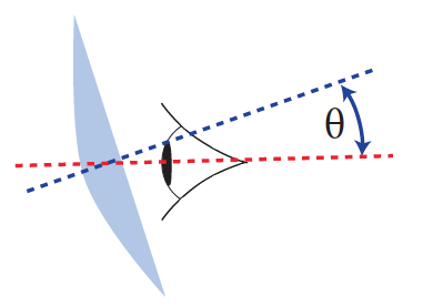 Figure 22: Lens with pantoscopic tilt θ
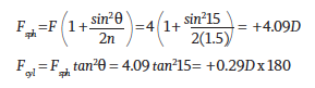
This will induce unnecessary power error and oblique astigmatism which can easily be calculated in our +4.00DS example as follows:
To avoid reintroducing this unnecessary aberration, the true pantoscopic angle must be determined (the angle between optical and visual axes) and the optical centre dropped from pupil centre by h (in mm) where the pantoscopic angle P=2h (figure 23). 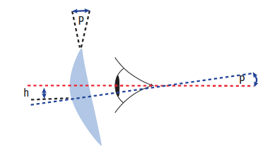 Figure 23: Derivation of true pantoscopic tilt
In other words, the optical centre is dropped 1mm for every 2˚ of tilt, so that the lens is positioned in the frame such that both the visual axis of the eye and the optical axis of the lens coincide in one direction of gaze (figure 24).
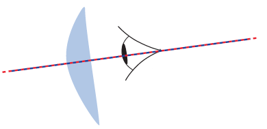 Figure 24: Coincident visual axis of the eye and the optical axis of the lens
Atoric Lenses
Aspheric surfaces are rotationally symmetrical and are often only employed on one surface of the lens because the other surface, on which any prescribed cylinder is to be worked, utilises conventional surfacing methods. It is, however, possible to utilise aspheric geometry in each meridian of a toric surface. Such surfaces, and the lenses which incorporate them (such as the Zeiss Hypal) are said to be atoric and compensate for off-axis aberrations in all directions of gaze to provide the best possible optical performance.
Conclusion
Aspheric lenses are the only optically correct lenses across the entire prescription range and the only best form lenses for moderate to high hyperopia. They are also significantly thinner and lighter. However, the most striking benefit is that aspheric lenses are much flatter and, being so much less bulbous, perhaps by as much as 50%, the most attractive option cosmetically. They appear to be much thinner than they really are and, with less distortion and less spectacle magnification, make the eye of the wearer appear more natural to the observer.
There are, however, some downsides. The flatness of the lens tends to cause greater problems with reflections and an anti-reflection coating is obligatory. Also, patients who wear spectacles for reading, especially in higher powers, may miss the near vision effectivity error that they would experience with standard lenses. Although aspherics are optically correct for near vision without carefully set expectations of adaptation, the patient may not be prepared to benefit from thinner, flatter, lighter lenses if they immediately feel the near vision has been compromised without warning. Also, low vison patients may miss the spectacle magnification of previous spherical lenses. This will be greatly reduced with aspherics.
Finally, aspheric lenses and lenticulars test the skills of the dispensing optician and optometrist as they require utmost accuracy of refraction and dispensing measurement, full knowledge of their limitations such as the inability to obtain prism through decentration, and a firm understanding of why the centre of rotation condition is vitally important. Overall, lenses that are better than best form should be everyone’s first choice.
Useful reading
The following texts have been used in the compilation of this article;
- Alonso, Jose, Gomez-Pedrero, Jose A and Quiroga, Juan A. Modern Ophthalmic Optics. Cambridge : Cambridge University Press, 2019. ISBN 978-1-107-11074-8.
- Brooks, Clifford W and Borish, Irvin M. System for Ophthalmic Dispensing. St Louis, Missouri : Butterworth Heinemann Elsevier, 2007. ISBN 978-0-7506-7480-5.
- Fowler, Colin and Latham Petre, Keziah. Spectacle Lenses: Theory and Practice. Oxford : Butterworth Heinemann, 2001. ISBN 978-0-7506-2370-5.
- Jalie, M. The Principles of Ophthalmic Lenses. 5th. London : Association of British Dispensing Opticians, 2016. ISBN 978-0-900099-02-1.
- Jalie, Mo. Ophthalmic Lenses and Dispensing. 2nd. London : Butterworth-Heinemann, 1999. ISBN 0 7506 5526 7.
- Millodot, Michel. Dictionary of Optometry and Vision Science. 8th. s.l. : Elsevier, 2018.
- Pedrotti, Frank L, Pedrotti, Leno M and Pedrotti, Leno S. Introduction to Optics. Cambridge : Cambridge University Press, 2018. ISBN 978-1-10842826-2.
- Sasian, Jose. Introduction to Lens Design. Cambridge : Cambridge University Press, 2019. ISBN 978-1-108-49432-8.
- Yacoubian, Araz. Optics Essentials. An interdisciplinary guide. Boca Raton, Florida : Taylor & Francis, 2019. ISBN 978-0-367-37791-5.