Visual task analysis is a vital aspect of both optometric examination and ophthalmic dispensing if a patient’s visual needs are to be understood and truly satisfied, yet it is often not given the attention it deserves. It is easy to ask a patient what they do for a living and make assumptions about their visual needs, whereas a change of tack by following up with ‘and what does your job involve?’ may reveal surprising results.
A job role such as ‘farmer’ may conjure up assumptions that are no longer appropriate. For example, the cab of a 21st century tractor or combine harvester often houses four or more computer monitors/touch-screen controls that are often positioned above and below as well as at eye level and pose significant challenges to the presbyopic patient (figure 1). Seeing at all distances in every direction of gaze is most easily satisfied with simultaneous vision multifocal contact lenses. However, bringing in the harvest can often mean working days and hence wearing times extending to 18 hours or more, and even with a modern air conditioned cab, harvesting grain is a dirty and dusty business. Protection of the eyes from small high speed particles is also a consideration. So it can be seen that task analysis is often complex, and the ability to satisfy a patient’s visual requirements with one optical appliance unlikely, particularly if the patient is presbyopic.
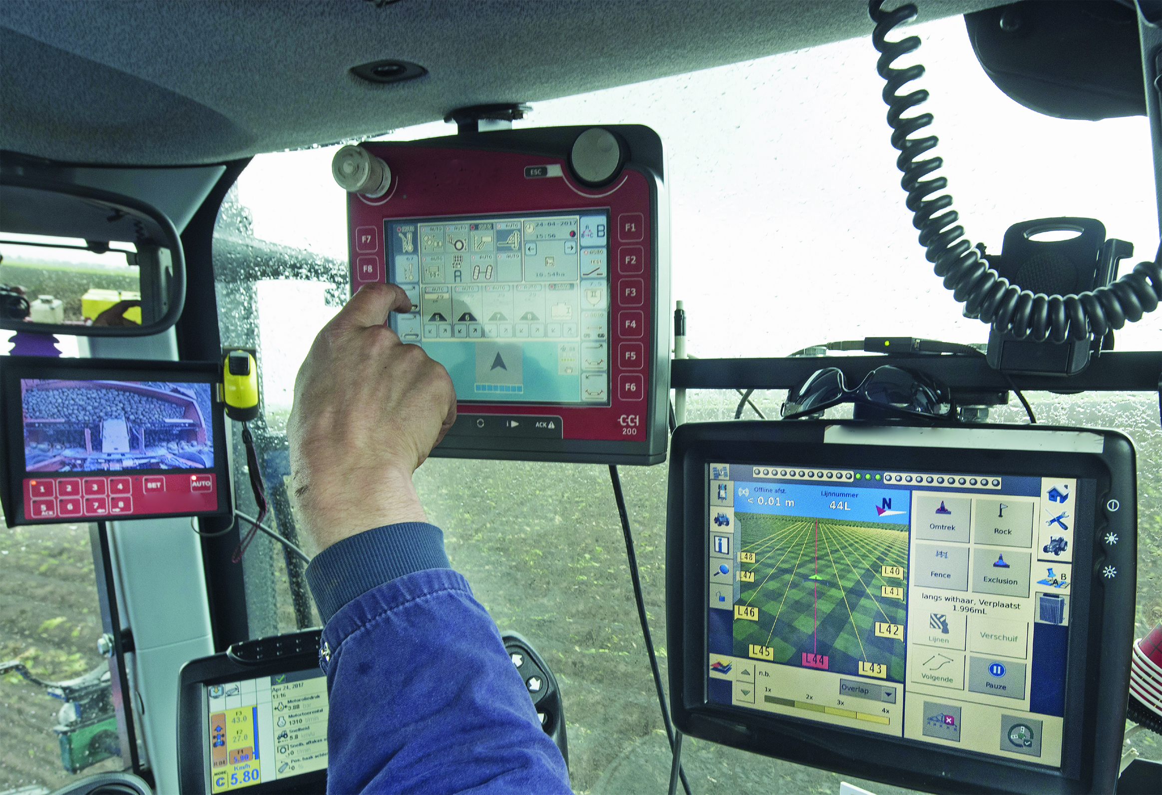 Figure 1: Modern computer controls at varying heights relative to the user pose significant challenge to presbyopic patients
In addition to obvious factors such as accuracy of prescription, working distances and direction of gaze, the practitioner must also consider typical and atypical optometric measurements such as best corrected visual acuity, amplitude of accommodation and fusional reserves. The optometric measurements must be related to the physical environment (and any hazards therein) and the task being analysed in order to come to an appropriate conclusion and give sensible advice.
Ergonomics is the study of people’s efficiency in their working environment and it has long recognised that comfortable clear vision is essential to the efficient performance of tasks. Clear vision can be negatively impacted by a variety of factors such as light levels, glare, poor contrast, inappropriate optical appliances and poorly designed working environments.
The Covid-19 pandemic has led to unprecedented numbers of people being forced to work from home, and many have come to appreciate the benefits of health and safety regulations now they have been deprived of well-designed offices and workstations. Others, essential workers at the frontline of retail, health and social care, soon appreciated the need for an optical appliance that did not steam up when worn with personal protective equipment leading to increased sales of anti-fog lenses and cleaning products and an increased demand for contact lenses (often unsatisfied due to social distancing rules).
The need to see as clearly as possible can cause workers to adopt unnatural postures that can quickly lead to health issues such as neck, back and shoulder pain. These can be alleviated by a combination of interventions such as occupational spectacle lenses, personally adjustable seating and careful thought as to the positioning of manual tasks and display screen equipment. It is also essential to ensure that the level of illumination is appropriate if a task is to be completed safely, without injury or other negative consequences such as headaches or asthenopia, and accurately, without error, and as quickly as possible for maximum efficiency and productivity.
Illumination
Illumination, both in terms of ambient background light levels, and the light levels required for specific tasks, is an essential aspect of visual task analysis. Patients of different ages will require different light levels for the same task, with older presbyopes of working age requiring around three times the light levels of young adults to perform the same task. Patients living with low vision will likely, though not necessarily, require even more.
Fortunately, illumination in the workplace and public spaces is strictly governed and a casual perusal of British Standards online (www.bsol.bsigroup.com) reveals literally hundreds of British, European and International standards specifying everything from the low-level emergency lighting found on aeroplanes and passenger ships, to specifications for the luminance and contrast of visual acuity test types (BS4274-1:2003).
Household lighting was once quite straightforward. Consumers had a choice of incandescent tungsten filament bulbs whose light output was directly linked to the power in watts, or where aesthetics were less of a concern, fluorescent tubes. The latter provided bright and even illumination over a wide area at a lower cost and found favour in the home, (particularly in rooms where high levels of illumination are important, such as kitchens and garage workshops), as well as dominating most workplaces.
Photometry
The science of the measurement of light is known as photometry and is concerned with the luminous energy emitted by light sources that stimulate the sensation of human vision. It is not concerned with the measurement of invisible radiations, such as ultraviolet, infrared and gamma rays, which fall within a related discipline; radiometry. A quick internet search reveals photometry to have many applications in science, from the measurement of the speed of rotation of distant stars to the analysis of light passed through liquids to determine the stage of chemical processes (in the brewing of beer, for example) to finding out the chemical composition of unknown samples of materials. At the cutting edge, radiometry and photometry have enabled many scientific discoveries and can involve dense and difficult mathematics beyond the training of the average registered optician.
Nevertheless, even at the basic level required of optical students and qualified ECPs, photometry is a subject that most ophthalmic dispensing and optometry students do not like, and many tend to forget about once qualified. Yet it contains important concepts essential for properly meeting the needs of patients, especially those with low vision, and also has application in the correct design of the environment, from frame displays to test charts and general illumination levels in the different areas of the practice.
Luminous flux and power
A light source emits a continuous stream of luminous energy. The amount of luminous energy emitted per second is known as luminous flux, Φ, (small Greek letter phi). The unit of luminous flux, Φ, is the lumen, symbol LM or lm.
The expenditure of energy relative to time is known as power. Historically, up until about the turn of the 21st century, light bulbs were of the incandescent tungsten filament type and were labelled according to standard power consumption – the most common being 40, 60 and 100 watts (W).
The lumen therefore is a unit of power, and experiment has shown that 1W is equivalent to approximately 621 lumens of green light (λ = 554nm).
Power consumption, however, is not the same as power output. Conventional incandescent light bulbs waste a lot of power as heat, so light sources of similar luminous flux can have very different power consumption, and the pressure to halt global warming and reduce carbon dioxide emissions (a biproduct of burning fossil fuels to produce electricity) has led to conventional incandescent light bulbs being phased out except for specialist uses where alternatives are yet to be developed (eg oven lights).
So called ‘low energy’ lamps have many different designs and technologies and the power consumption is no longer a reliable guide to the light output as it was with tungsten filament lamps. Lamps (light bulbs) are therefore now labelled in lumens.
A 5W low energy replacement for a 40W E14 (small Edison screw fitting) bedside lamp is labelled as emitting 400LM and said to be equivalent to a 45W incandescent bulb or a 15W compact fluorescent. Sample packaging labels are shown in figure 2.
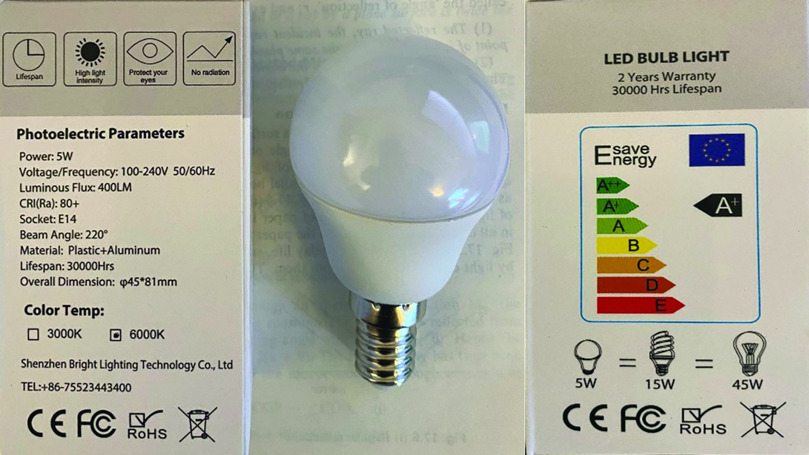 Figure 2: A 5W low energy replacement for a 40W E14 lamp
A 4.2W low energy replacement for a 50W GU10 lamp (halogen spotlight bulb) commonly used in practice displays emits the same luminous flux at 345LM. Figure 3 shows the packaging for such a bulb – it is interesting to note the manufacturer’s need to explain the lumen to prospective purchasers.
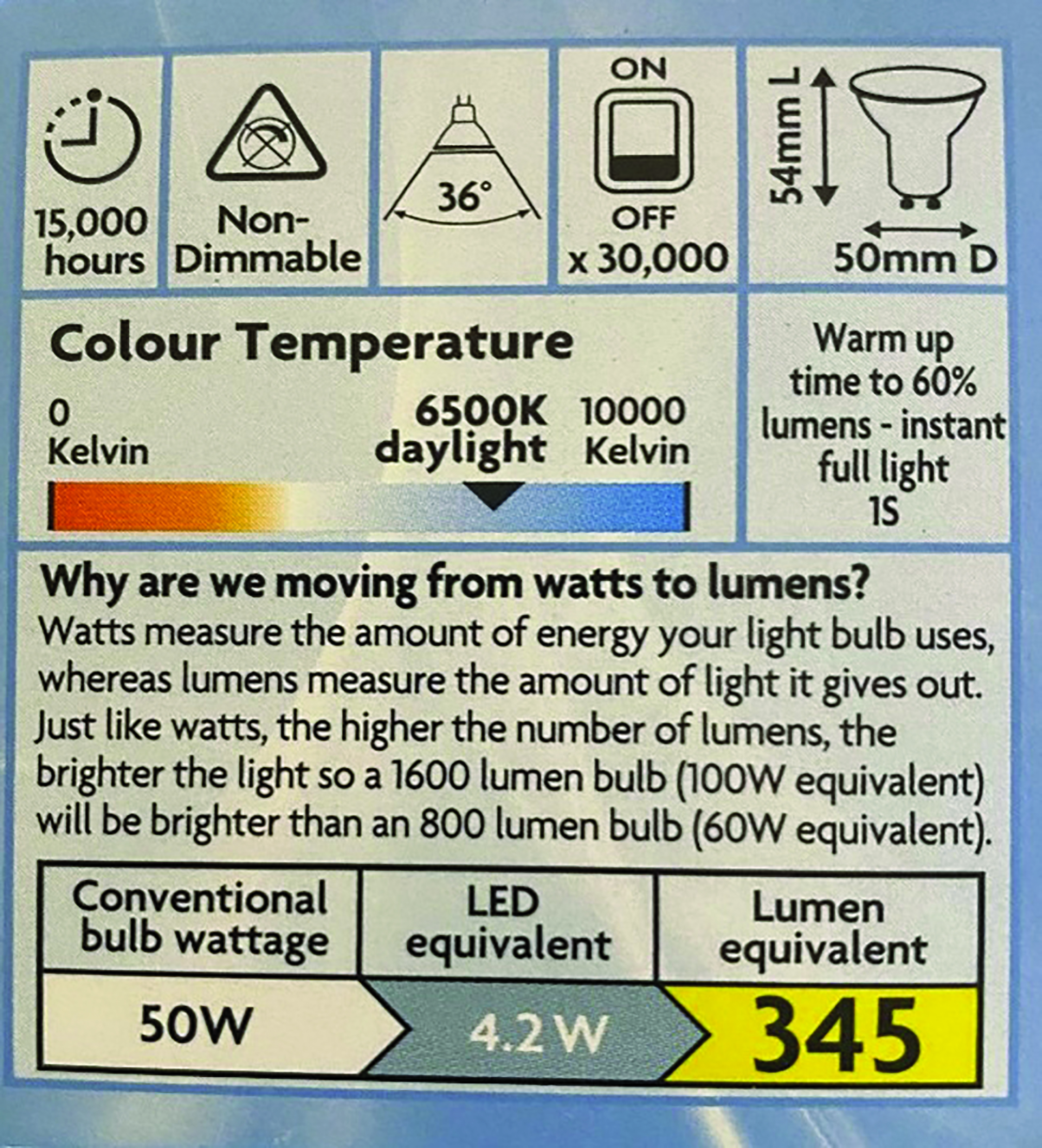 Figure 3: A 4.2W low energy replacement for a 50W GU10 lamp
A light source such as the sun, or the filament of an incandescent lamp (light bulb), radiates luminous flux in every direction around it. If we consider a small point light source, S, and a specific direction, say left to right, indicated by SA in figure 4, an amount of luminous flux, φ, is radiated in a small cone of solid angle, ω, (small Greek letter omega). The cone is drawn about the line SA, with S as its apex and A as the centre of its base.
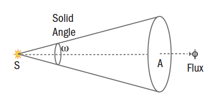 Figure 4: Luminous flux
Solid Angle
Photometry calculations must take into account the ability of light to radiate in any direction in three-dimensional space. A ‘floating’ light source such as the sun quite literally radiates light in all directions. However, artificial light sources can never truly do so since some aspect of the source (the wire or base of a lamp or the body of a candle) will cast a shadow, or absorb or reflect some portion of the light emitted. In ophthalmic optics, we are mainly concerned with approximations and general principles rather than exact levels of illumination and so, for simplicity, we generally only consider point sources of light.
There are many systems for the measurement and calculation of solid angles. The most popular seem to be steradians and square degrees, the three-dimensional versions of the two-dimensional angular measures radians and degrees respectively. It is remarkable that the understanding of this subject was first developed by the philosophers of ancient Greece, later refined by mediaeval Muslim mathematicians, centuries before the invention of calculators and computers. Yet these early thinkers were able to plot the passage of planets and stars through space and predict their daily positions centuries into the future.
At the scale of household/workplace illumination, steradians are the more useful measure of solid angle. The steradian, 1sr, is defined as the solid angle contained by a circular area of 1m2 on the surface of a sphere of radius 1m. There are 4π steradians (12.566sr) in a sphere since the surface area of a sphere is 4πr2.
Steradians are difficult to visualise, not in the least because it is difficult to imagine the areas on the surface of a sphere fitting neatly together, a series of parts adding up to a whole, in the way two-dimensional angles would add up to form a 360-degree circle. Nevertheless, it can be appreciated that if a sphere occupies 4π steradians (12.566sr), a hemisphere must occupy half of this amount (2π or 6.283sr). So, a point source in space would radiate light over 4π sr (so, in all directions), whereas a point source acting as a ceiling light would only radiate light across 2π sr (in all the directions downwards below the level of the ceiling).
It may be helpful to visualise a common approximately spherical object such as an orange (figure 5a). From the centre of the fruit the surface skin of the orange subtends 4π sr. If the orange is now cut in half, then the skin on each hemisphere subtends 2π sr.
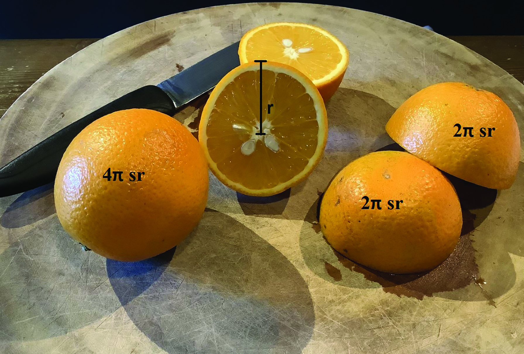 Figure 5a: For oranges of radius r, the surface subtends 4π steradians (sr). If the orange is now cut in half, then the skin on each hemisphere subtends 2π sr.
If the half-orange is cut in half again, at right angles to the cut-surface, then the skin of the quarter orange would subtend π sr. This is equivalent to placing a point source midway along a wall at the intersection of the wall and ceiling – light can radiate out from the wall in any direction below the level of the ceiling.
Finally, if the quarter orange is cut in half across its length then the resulting eighth is analogous to placing a point source of light in the top corner of a room where two walls meet and intersect with the ceiling. Light shining from this point source would illuminate a solid angle of π/2 sr (figures 5b and 6).
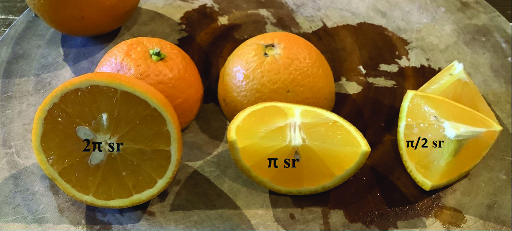 Figure 5b: Solid angle illumination from a half, a quarter and an eighth segments.
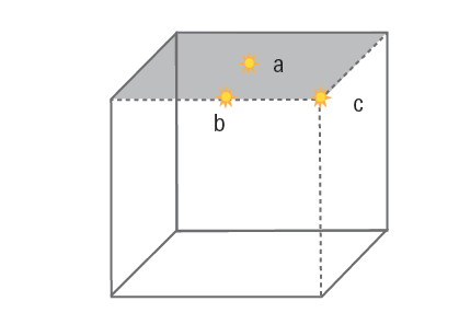 Figure 6: A representation of a room with the ceiling, viewed from below, shaded grey. Point light sources placed at a, b and c radiate light through 2π, π, and π/2 steradians respectively.
One frustrating aspect of illumination is the use of easily understood two-dimensional ‘beam angles’ on lamp packaging such as those shown in figures 2 and 3. Conversion between steradians and beam angles and vice-versa is not easy mathematically and is complicated by the fact that the area of the spherical surface is curved rather than flat. For small beam angles, we can assume that the surface is flat for ease of calculation of the area of the base of cone, and and extending the radius of the sphere to one metre will give an approximation of the steradians equivalent. If the cone illustrated in figure 4 had a beam angle of 36 degrees like the lamp in figure 3, the radius of the base would be tan 18 or 0.325m, and its area would be 0.33m2. From this we we can deduce that the beam occupies (very approximately) one third of a steradian. With the other lamp (in figure 2), we cannot use such an approximation for a beam angle of 220º. Conversion of beam angles to steradians is most easily done using an online calculator such as available at; http://smart-unit-converter.com/angle-converter.php.
Luminous Intensity
The luminous intensity, I, of the lamp, is defined as the ratio φ/ω, that is the luminous flux per solid angle. Since solid angles are measured in steradians, (symbol sr), then the unit of luminous intensity is lumens per steradian (lm sr-1), also known as the candela (cd). The candela is the agreed Standard International (SI) Unit of visible light from which the other terms are derived.
It is important to realise that the luminous intensity does not vary with distance from the source. A good analogy is to imagine a shower head (figure 7) from which flows an amount of water per second (the equivalent of flux). Assuming the jets of water diverge, then as we move further away from the shower head the same jets of water would occupy a larger area within the same solid angle, so the amount of water per solid angle remains the same. If we then imagine holding close to the shower a small bath sponge just big enough so that every jet hits it, if we then moved the sponge further away we would discover that the number of jets incident upon it would reduce as the distance from the shower head increases, so the number of jets per unit area, or the incident water per unit area is reduced.
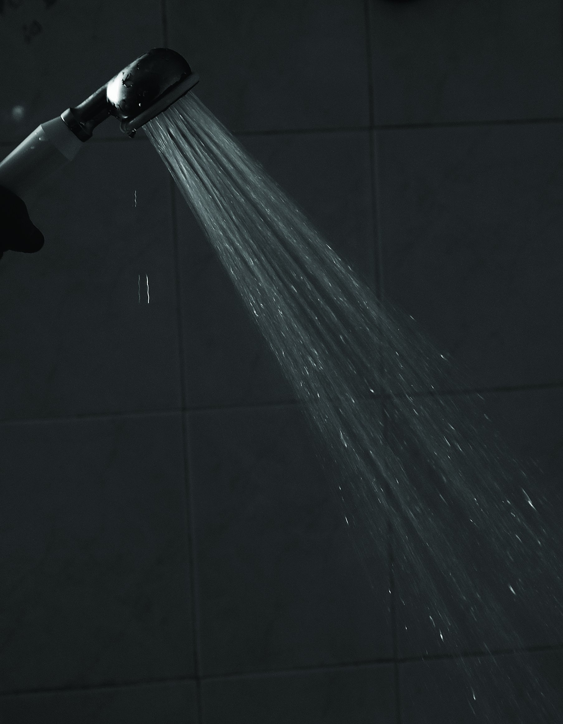 Figure 7: Divergent jets of water from a shower head are analogous to
light from an extended source.
Returning to light, using simple geometry, we can see that within the bounds of a cone of solid angle, and importantly assuming a point source at the apex of the cone, if the distance, d, doubles, then the diameter, and therefore the radius, r, of the area the light is incident upon also doubles. And since the area of a circle is proportional to r2, if the radius doubles then the area will increase fourfold. It therefore follows that the amount of light incident on a given amount of area (the illuminance) will be reduced by a factor of four.
Illuminance
The flow of light, or luminous intensity, I, per unit area, A, is known as the illuminance, E, where:
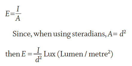
This is the basis of the most commonly used law of illumination in everyday practice; namely, the inverse square law. This states that the luminous intensity per unit area is inversely proportional to the distance from the source. In other words, if the distance of a task from the light source is halved then the illuminance will be quadrupled. If the distance is reduced by two-thirds then there will be a nine-fold increase in illuminance. The formula can be re-arranged to:
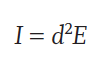
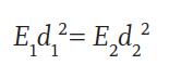
And since luminous intensity, I, remains constant for every distance, a sometimes more useful equation is:
Case study — the Inverse Square Law of Illumination
As a result of advancing cataracts, Ethel is no longer able to read using the ‘big light’ – a 150 watt equivalent bulb mounted in the ceiling 2m above her reading material. Ethel transfers the light bulb from the ceiling light into a suitable angle-poised lamp a distance of 40cm from her book. Assuming that the page in each case is inclined at the same angle to the light, what is the increase in illuminance?
Let the ceiling light have an arbitrary illuminance, E1 of 1. 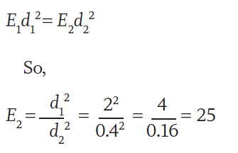
Moving the light closer to one-fifth of the distance increases the illuminance 25-fold. The inverse square law is a simple, and often forgotten, way of improving any patient’s near vision. Though there is no guarantee here that Ethel’s near vision will be restored to its former levels, with most low vision patients, and other patients experiencing reading difficulties, even with a new up to date prescription, improving illumination will almost always improve near visual acuity and/or comfort. For ease of calculation, this case study is contrived. In practice, it is essential that task lighting is in addition to ambient room lighting, not instead of it. This avoids difficulties adapting to highly differing levels of illumination when moving around.
The Cosine Law of Illumination
In the case study, it was stipulated that, in each situation, Ethel inclined her reading material towards the light source at the same angle, since illuminance varies with the angle of incidence according to Lambert’s cosine law:
where θ is the angle of incidence. It can be seen that maximum illuminance occurs when the object under gaze is positioned at right angles to the incident light such that the angle of incidence zero. Since cos 0 = 1 then E will be at a maximum.
Task Lighting
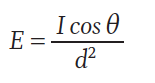
The practical application of the cosine law of illumination is to ensure that task lighting is positioned as close to the visual axis as possible such that the object can face both the light source and the eye as much as is possible. Traditionally, low vision patients have been advised to have task lighting positioned such that it shines from over their shoulder for this reason (figure 8). Low vision patients also need high levels of ambient room light of around 1,000 Lux if they are to avoid problems of adaptation moving between areas with different light levels, and see obstacles such as steps and furniture.
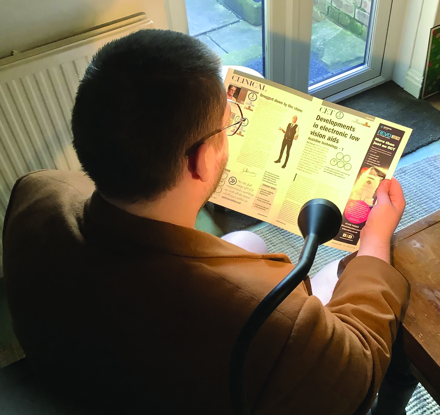 Figure 8: An over the shoulder task light dramatically improves illuminance
Modern light weight LED lighting offers many more practical solutions including USB powered/rechargeable lights that can clip on to desk edges, bed headboards, or even the reading material itself, especially if used with a clipboard to facilitate this (figure 9).
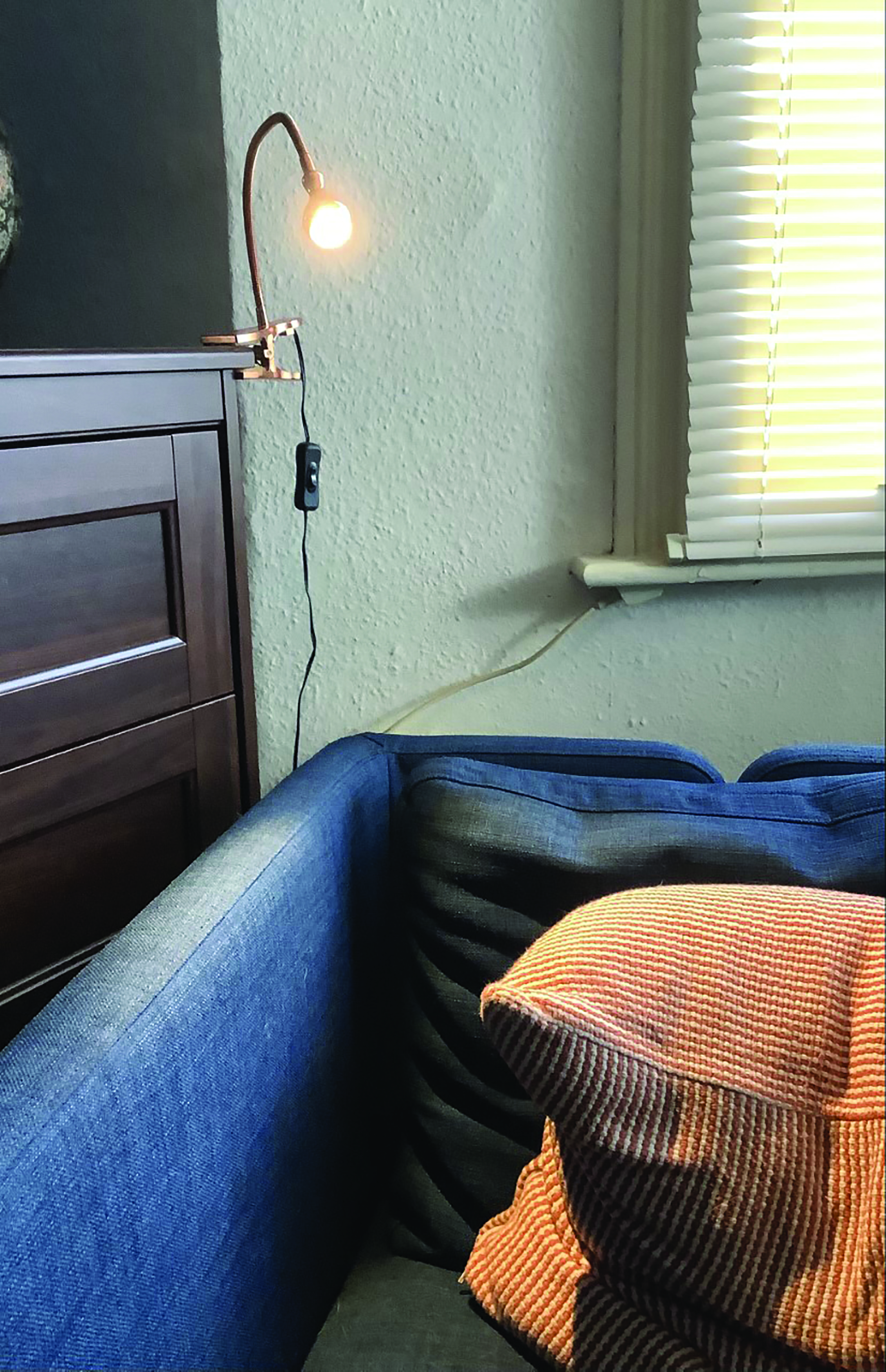 Figure 9: A clip-on LED task light available for just a few pounds
is an ideal solution for many low vision patients
Light weight and computer-controlled components enable lighting designers to address many issues. LED technology can provide the ability to select for different brightness levels and colour temperatures (daylight, cool blue/white and warm yellow/white) to suit the individual requirements of the user (figure 10). Compared to fluorescent lights LED technology offers great flexibility for lighting manufacturers to design aesthetically pleasing solutions. Figure 11 shows for example how an extended light source can provide even illumination of reading material over a wide area, ideal when reading a newspaper for example.
 Figure 10: Adjustable LED desks lights allow the user to select the brightness level and colour temperature to suit their individual needs
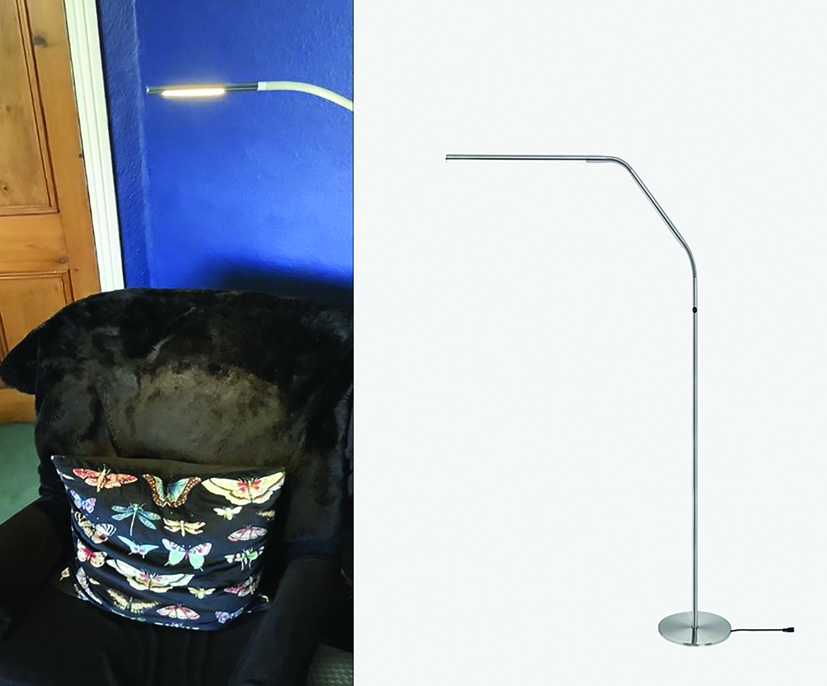 Figure 11: An extended LED light source (right) provides more uniform illumination of reading material over a wider area source (left)
Low vision patients who are registered as sight or severe sight impaired are normally provided with a home visit to assess their needs. This may be from a sight loss rehabilitation officer or an occupational therapist. Patients often report that one of the most useful lighting additions to their household following such visits is the addition of under-cupboard lights in the kitchen (figure 12). Such lights often incorporate lamps with similar luminous flux power output (lumens) as ceiling lights but are clearly much closer to the task such as chopping food and reading cooking instructions.
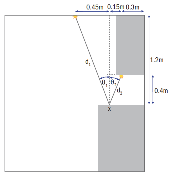 Figure 12: Under-cupboard lights (inset) greatly increase
the illuminance of work surfaces
Case study – Under-cupboard kitchen lighting
Val has AMD and following an assessment provided by social services has under-cupboard lighting fitted. Her kitchen is a small ‘galley’ kitchen just 1.8m wide with a 600mm work surface along one side with wall cupboards, 350mm deep placed 400mm above. The kitchen is lit by a single point source light of 350 Lumen placed centrally in the ceiling (height 2.1m). Following the sight loss support assessment, it is decided to place an under-cupboard light, also of 350 lm, 300mm from the wall in the same vertical plane as the ceiling light at right angles to the work surface as shown in figure 12.
It is a straight-forward matter to calculate how much greater the illumination will be of a point X on the worksurface, shown in figure 12, 150mm from the front edge.
The illumination from the ceiling light can be calculated as follows from figure 12:
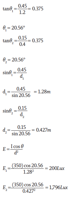
It can therefore be seen that the under-cupboard light illuminates the point on the work surface nearly nine times more brightly than the ceiling light, and that the combination of the two will provide a 10-fold increase in illumination. Sight impaired patients are at much greater risk of cutting, burning or scalding themselves in the kitchen and illumination is a key component of reducing the risk.
Luminance
So far illuminance has been considered, that is the light incident on an object. The visibility of the object will also depend on its luminance, that is the light that is reflected or emitted from its surface. A simple example of the difference is to imagine two identical classrooms, one with a black chalkboard at the front, and another with a whiteboard. Despite identical illumination the two boards will have very different luminance. The luminous intensity reflected from the whiteboard will be very much greater than that reflected from the blackboard. Table 1 shows the luminance levels of a variety of white light sources. It can be seen that the human eye can easily adapt to luminance levels varying by a factor of around 106 from viewing objects in bright sunlight to viewing the same object in moonlight.
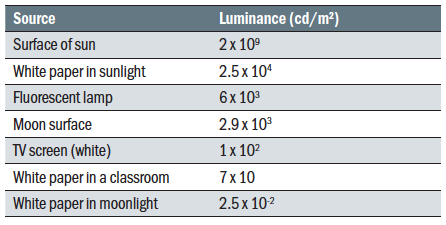 Table 1: Luminance values of everyday light sources (adapted from Tunnacliffe and Hirst, 1996)
Light sources emit light, whereas when light is incident on other objects it may be absorbed, transmitted, or reflected such that an object becomes a source in its own right. Reflection may be specular, as from a mirror or highly polished surface, or diffuse, where reflection is random and in all directions such as from a matt painted surface. Reflectance is the ratio of luminance, L, to illuminance, E.
Where light availability is at a premium for the patient to obtain the best visual acuity possible it is also important to think of how spectacles impact the amount of light available. Patients who prefer photochromic lenses outdoors may be better with a clear pair for indoor use as this would increase light levels by around 15-20%. Even on clear lenses the use of an anti-reflection coating increases light levels by more than 8% in CR39 and 11% in polycarbonate and also improves contrast by removing the veiling effect of unwanted reflections.
While calculations are concerned with point sources of light the real world involves extended sources, and light levels indoors are impacted greatly by the environment. White ceilings are important in maximising illumination, and lighter coloured
furnishings will result in greater ambient light levels than darker colours due to the greater reflectance. This needs to be taken into account when refurbishing a practice or decorating a room in a different colour scheme.
Recommended lighting levels
There is much disagreement between sources as to the recommended lighting levels. Table 2 is a composite of values from the different sources in the bibliography. It is reported that a 55-year-old presbyope requires approximately twice the illuminance compared to a 40-year-old pre-presbyope, and adults of pension age are likely to require four or five times the light levels compared to children or young adults. When designing practices or advising patients on illumination it is prudent to err towards the higher end of the scale where a range is stated.
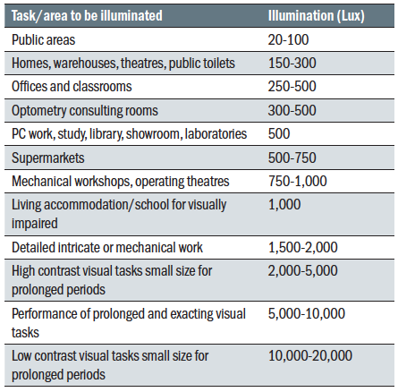 Table 2: Recommended illuminance for a variety of tasks
Conclusion
An understanding of lighting and the essentials of photometry, including especially the inverse square law and the cosine law, is a core competency for all eye care practitioners. Correct illumination enables all patients to get the best from their optical appliance in the indoor environment, and for many is the difference between being able to complete a task or not, or the factor that makes vision clear comfortable and, by association, more enjoyable.
Since ECPs are in the business of helping people of all ages (including the visually impaired), it seems prudent that shop floor areas, corridors and stairs within optical practices should be illuminated sufficiently to cater for the needs of all patients and a level of 1,000 Lux is recommended. Clearly, pre-screening and sight test rooms need adjustable levels of illumination, but practitioners should be aware that low vision patients may struggle to navigate areas with low light levels and may need help in the form of clear specific instructions or physical guiding. Practice design should also take into account the levels of light required by presbyopic staff. 2,000 Lux is appropriate when carrying out exacting tasks such as inspecting finished spectacles for scratches, assembling spectacles, or carrying out repairs.
Peter Black MBA FBDO FEAOO is senior lecturer in ophthalmic dispensing at the University of Central Lancashire, Preston, and is a practical examiner, practice assessor, exam script marker, and past president of the Association of British Dispensing Opticians.
Useful Reading
The following texts have been used in the preparation of this article:
- MacNaughton, J. The practical management of visual impairment. (2018). Clearview Training
- Tunnacliffe, A. Hirst, J. Optics. (1996) ABDO. Ch.9.
- Dickinson, C. Low vision principles and practice. (2002). Butterworth Heinemann
- Zeiss Handbook of Ophthalmic Optics. (1988).
- Innes, M. Lighting for Interior Design. (2012). Laurence King
