[CaptionComponent="2851"]
Putting clinical matters to one side for a moment, it is important that practitioners remember that in most cases the end result of the time we spend with most patients is to supply them with a new optical appliance. Apart from the labyrinth of clinical regulations and guidelines that we must all adhere to, the act of supplying our patients with ‘goods’ means that we must also be aware of relevant consumer legislation.
When a patient purchases an optical appliance from a practice a contract of sale is formed between the patient and the practice. The essence of this contract is that the practice agrees to supply a specific product at an agreed price and the patient agrees to purchase that product. A contract of sale may be made in writing, or by word of mouth, or partly in writing and partly by word of mouth, or may be implied from the conduct of the parties. If the practice fails to provide the agreed product or the patient fails to collect and pay for the product the contract is broken. The primary item of legislation that most consumers will be aware of is the Sale of Goods Act 1979. The key points of interest are:
- Wherever goods are bought they must ‘conform to contract’. This means they must be as described, fit for purpose and of satisfactory quality, ie not inherently faulty at the time of sale
- Goods are of satisfactory quality if they reach the standard that a reasonable person would regard as satisfactory, taking into account the price and any description
- Aspects of quality include fitness for purpose, freedom from minor defects, appearance and finish, durability and safety
- It is the seller, not the manufacturer, who is responsible if goods do not conform to contract
- If goods do not conform to contract at the time of sale, purchasers can request their money back ‘within a reasonable time’. However, this is not defined and will depend on circumstances
- For up to six years after purchase (five years from discovery in Scotland) purchasers can demand damages (which a court would equate to the cost of a repair or replacement)
- A purchaser who is a consumer ie is not buying in the course of a business, can alternatively request a repair or replacement
- If repair or replacement are not possible or too costly, then the consumer can seek a partial refund, if they have had some benefit from the goods. A full refund could be justified if the fault/s has meant they have enjoyed no benefit
- In general, the onus is on all purchasers to prove the goods did not conform to contract (ie were inherently faulty) and should have reasonably lasted until this point in time (ie perishable goods do not last for six years)
- If a consumer chooses to request a repair or replacement, then for the first six months after purchase it will be for the retailer to prove the goods did conform to contract (ie were not inherently faulty)
- After six months and until the end of the six years, it is for the consumer to prove the lack of conformity.
From the above points, we can see that although these acts are intended to protect both the consumer and seller, the pursuit of a claim can prove to be a difficult, time-consuming and often an expensive endeavour for both sides. So how can practitioners protect themselves and reduce the chances of a patient returning to complain about an optical appliance? In most instances complaints can be avoided by the provision of an adequate quality control system throughout the manufacturing, assembly and verification processes.
The completed pair of spectacles that a practice supplies to a patient often comes from more than one supplier with the frame being ordered from one supplier, the lenses from another and the assembly, cutting, edging and fitting having been carried out either in-house or by a third party. It is vital therefore, that we verify every aspect of the finished appliance prior to the patient arriving to collect their new spectacles.
Verification
The measurement of spectacle lens power
The measurement of spectacle lens power is of course undertaken with the use of a focimeter which is designed to measure the vertex power of a spectacle lens. A spectacle lens has a back and a front vertex power and both of these values can be measured using a focimeter. When a spectacle lens is placed in the focimeter with its back (concave) surface in contact with the lens support, the instrument records the back vertex power of the lens. This is the value which is usually required in practice, since spectacle lenses and trial case lenses are numbered in terms of their back vertex powers. If the spectacle lens is reversed so that the front (convex) surface of the lens is in contact with the lens support, the instrument records the front vertex power of the lens. The front vertex power of a spectacle lens is of interest when measuring the reading addition of multifocal and progressive power lenses. Three main types of focimeter may be found in optometric practices and laboratories.1 These are the traditional manual eyepiece focusing instruments that employ an astronomical telescope, projection focimeters that focus the image on a screen and automatic electronic focimeters. The original design was the conventional eyepiece focusing instrument which is still widely used today and is cheaper to purchase when compared to electronic devices. Before using a conventional focimeter it is important to focus the eyepiece to achieve accurate measurement. This is necessary to ensure that parallel light is leaving the telescopic viewing system of the instrument. The focus of the eyepiece should be checked before each use particularly if there are multiple users of a single instrument in a practice. A suggested procedure is as follows. Rotate the power control so that the instrument is reading zero. While viewing the target, unscrew the eyepiece until the image goes out of focus then, screw in the eyepiece until the image is just in focus. Adjust the power control and check that the target and eyepiece graticule are in focus at the zero position on the dial. This procedure is particularly important for younger users as the main variable is available accommodation.
Each type of focimeter has its advantages and disadvantages and all must be used correctly to obtain accurate results. However, the main advantage of projection and electronic focimeters is that they eliminate the need for eyepiece focusing. Electronic focimeters are perhaps better suited for verifying large numbers of appliances on a daily basis especially when multiple users are involved and are often found in large practices and laboratories.
There are two other variables involved in the design of a focimeter which relate to the focal point of the focimeter’s measuring system. If the focal point of the focimeter’s measuring system remains on the optical axis of the instrument the system is known as a ‘Focus on Axis’ (FOA) focimeter which is found in manual focusing focimeters. While some automatic focimeters also use an FOA design others employ an ‘Infinity on Axis’ (IOA) design in which the focal point of the lens being measured goes off the axis of the instrument when the lens incorporates a prismatic element. In the absence of prism these two designs will give the same results. However, the two designs may give different results when moderate to strong positive lenses are measured.2
Tolerances
When checking prescription lenses it is important to be aware of the current standard for lens tolerances. Since February 1 2010 the standard used in the UK for the verification of prescription spectacles has been BS EN ISO 21987:2009.3 This is a comprehensive and complex document and is unfortunately not always well understood by practitioners and staff involved in the verification of spectacles. The standard gives tolerances on the back vertex power of single vision, multifocal (bifocal and trifocal lenses), progressive and degressive power lenses; tolerances on the direction of cylinder axis, tolerances on the addition power for multifocal and progressive power lenses, prism imbalance tolerances for single vision, multifocal, progressive and degressive power lenses; lens thickness tolerance and lens positioning tolerances. The document also includes a section devoted to test methods. Unlike early standards for spectacle lens powers, tolerances are not applied to the prescription in sph-cyl form. Table 1 is reproduced from the tolerances for mounted single vision and multifocal lenses given in ISO 21987. A separate table in the document deals with progressive and degressive power lenses.
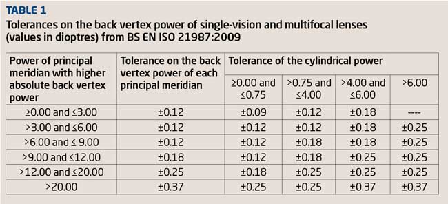
The tolerances for spherical lenses are relatively straightforward to apply. However, when dealing with astigmatic lenses we must first determine the power of the principal meridian with higher absolute back vertex power. Consider the prescription +4.00/-1.25 x 90. As the highest back vertex power is +4.00D (the other power being +2.75) we have to refer to the second row in Table 1 which informs us that the tolerance on the back vertex power of each principal meridian is ±0.12D. The maximum power must therefore lie within the range +4.12D and +3.88D and the minimum power within the range +2.87D and +2.63D. In addition, as the cylinder is between 0.75D and 4.00D the tolerance on the cylinder is given as ±0.12D. This is to prevent the situation where one meridian is strong by 0.12D and the second meridian weak by 0.12D, giving a cylinder of 1.50D. Using the above values, if the lens +4.00/-1.25 x 90 was measured and back vertex powers of +4.12D and +2.63D were recorded the lens under test would pass the first requirement of the standard. However, the cylinder produced by these two back vertex powers is 1.50D (4.12 – 2.63). As the permitted tolerance on the cylinder power is only ±0.12DC it fails, on the cylindrical power of the lens. Table 2 (again reproduced from ISO 21987) gives tolerances on the direction of cylinder axis.
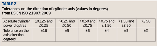
Compared to the 1998 edition of BS 2738 the tolerance of ±16 degrees which is now allowed on the axis directions of glazed cylinders up to ±0.25D appears excessive. In BS 2738 ±7 degrees was allowed on cylinder powers of up to ±0.50D. Reasons for the relaxing of tolerances on the direction of the cylinder axis have been provided by Rabbetts4 and Fowler.5
It is interesting to note that the American National Standards Institute (ANSI) uses a two parameter method (sphere and cylindrical power in minus cylinder transposition) rather than the ISO 3 parameter method described above.
The section of BS EN ISO 21987:2009 relating to centration and prism is, in the author’s opinion, intimidating to say the least. It is very complicated, consists of various instructions, a table of tolerances, two graphs, several strange values for some of the tolerances and again, in the author’s opinion and in the opinion of others impractical for use in everyday practice.5 The author understands that when the content of BS EN ISO 21987:2009 was being deliberated the UK group repeatedly presented a much simpler method which was not accepted by the project group.4 However, the UK’s technique, including a simple table giving the tolerances, is given as an alternative method in Annex C of BS EN ISO 21987:2009. The author also understands that the current standard is under revision.6
When measuring and verifying the power of a pair of spectacle lenses it is always wise to refer back to the prescription stated on the patient’s clinical record card (or equivalent) as this avoids the risk of missing a transcribing error when the order was written.
Compensated prescriptions
Thanks to the influence of freeform or digital surfacing with regard to both the industry and profession it is becoming increasingly common for manufacturers of spectacle lenses to ‘compensate’ a prescription with the aim of optimising lens performance and/or to allow for the position of the lens when worn. If compensation has taken place the power of the lens supplied will be different to the power ordered as the power of the lens supplied (the compensated prescription) will have been modified to allow for the effect of the lens in the ‘as worn’ position. In such cases the lenses will be returned from the supplier with details of the compensated powers that must be verified using a focimeter. These compensated powers should be checked against ISO 21987 in the usual way. A note of the compensated powers should be kept with the patient’s record in case of future verification or non-tolerance issues. The International Standards Body is in the process of introducing the term verification power to describe the powers that manufacturers will issue with lenses. The term measured values will then be used to denote the powers that are recorded once the lenses have been checked against the given verification power on a focimeter. These terms will eventually find their way into ISO documents.7
Single vision spectacles
The process of verification of a pair of single vision spectacles can be broken down into:
- The prescription, centration and prism
- Correct lens form
- Quality of surface treatments/coating, tint accuracy and photochromic performance
- Frame model, quality, colour and size
- Structural integrity.
Prescription, centration and prism
With the exception of compensated prescriptions, ideally the power of every lens supplied should be exactly the same as the prescribed values. However, as described in the previous section, tolerances of lens parameters are allowed to account for minor variations in manufacturing. BS EN ISO 21987:2009 provides these tolerances and is essential for every prescription house and optometric and dispensing practice. Members of the College of Optometrists may download this and other BSI publications from the BSI website free of charge. It is interesting to note that some of the major lens suppliers produce their own mounting tolerances which in some cases are more exacting than ISO 21987, for example, the tolerance on cylinder axis, and provide simplified tolerances on centration.
Lens form, material and refractive index
These items also conform to the notion of the finished spectacles being ‘fit for purpose’, since a modification in lens form from spherical to aspheric or full aperture to lenticular may result in the patient being unable to tolerate the change, and thus unable to wear the spectacles. A change in refractive index can affect off-axis vision again making the spectacles potentially difficult to wear. In addition to these clinical issues we should remember that the lenses must be ‘as described’. If the patient has paid extra for thinner, lighter lenses then that is what they should receive. In addition, the lenses should be free from scratches, stress and other surface defects.
Lens colour and surface treatments
Coatings should be verified using a suitable light source to ensure they are free from defects. Both lenses when treated with a reflection-free coating should display the same degree and shade of residual reflection. The dividing line of flat-top bifocals should be inspected carefully as the coating material can ‘run’ on the segment top. Tints should be verified against the samples used during the dispensing process or verified on a spectral analyser to confirm their performance characteristics. Photochromic lenses must be tested either outside in direct sunlight or under a UV lamp within the practice to ensure they react and darken evenly.
Frames
The frame supplied should be the same as the one ordered. In many cases it will of course be the same frame used at the time of the dispensing as most frames will be supplied from stock. However, it is good practice to ensure that the frame is ‘as described’ by verifying the manufacturer, style and/or the model number, colour and size. The finish should be examined to ensure that the frame is free from defects. Any specified alterations to the original frame such as a curl side conversion, ptosis prop, different nose pad design or material will also need to be verified.
Structural integrity
It is important to ensure that before supply the completed appliance is inspected to ensure that the lenses are secure, screws tight, sprung hinges work smoothly and the nose pads and end tips are secure.
Bifocals and trifocals
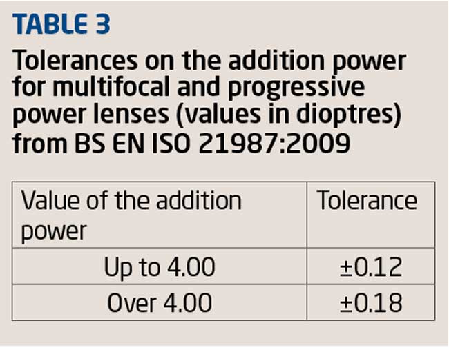
Although much of the verification process for multifocal lenses is the same as for single vision lenses, some additional attention is required in respect of the segment. BS EN ISO 21987:2009 gives tolerances for multifocal and progressive power lenses which have been reproduced in Table 3.
BS EN ISO 21987:2009 gives specific recommendations for the measurement of the addition for multifocal lenses. Unless otherwise specified by the manufacturer, the addition is measured on the segment side of the lens. So, if the segment (or progressive surface) is on the front surface of the lens then the addition is the difference between the front vertex power of the near portion and the front vertex power of the distance portion measured at a specific near reference point. If the segment (or progression) is on the back surface of the lens then the addition is the difference between the back vertex power of the near portion and the back vertex power of the distance portion. These vertex power measurements are taken at specific distance and near reference points and readers are referred to ISO 21987 for a detailed description of the method of measurement. Figure 1 illustrates the correct measuring position for a multifocal lens whose segment is located on the convex surface. The distance prescription is measured in the conventional way with the concave surface of the lens in contact with the focimeter stop (Figure 1a).
[CaptionComponent="2852"]
The lens is then reversed in the instrument so that its convex surface is in contact with the focimeter stop (Figures 1b and c). The difference between the front vertex powers measured at the distance and near reference points of the lens provides the near addition. Failure to adhere to this method for front surface multifocals can lead to significant errors particularly with positive lenses. In the case of astigmatic lenses measurements to determine the addition should be taken using either the focal lines of the target which lie nearer to the vertical, or the spherical equivalent power. Jalie8 reminds us that spectacle lenses, whether prescribed for distance or near vision, are numbered in terms of their back vertex powers. However, this system is really an unsound one when dealing with near vision.
Segment type, size and position should also be verified. This includes the intermediate segment of a trifocal lens as the depth of the intermediate segment is usually specified separately to the overall segment size. When a single replacement multifocal lens has been ordered the segment drop must be specified in order to avoid unwanted vertical differential prismatic effect. ISO 21987 provides positioning tolerances for multifocal lenses.
Progressive power lenses
Prior to the verification of any progressive or degressive lens it is necessary to refer to the correct template (provided by the supplier) for the lens under test (Figures 2a and 2b).
[CaptionComponent="2853"]
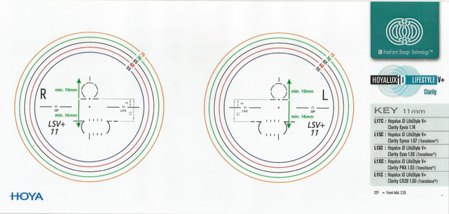
After accurately marking up the nasal and temporal reference points on each lens the use of the template allows the practitioner to:
- Verify that both lenses are horizontally aligned
- Locate and mark the distance and near vision zones prior to neutralisation (Figure 3, points D and N)
- Locate and mark the prism reference point.
[CaptionComponent="2854"]
When checking progressive power lenses it is important to measure values at the points specified by the manufacturer. When the lenses arrive from the supplier the relevant verification points are usually indicated on the lens by removable markings. It may be necessary to reconstruct the required points using a template. It is important to do this with some degree of care using a fine felt tipped pen. When measuring the back vertex power of a progressive power lens the concave surface must be placed in contact with the focimeter lens support and centred at the distance reference point specified by the manufacturer. ISO 21987 provides tolerances on the back vertex powers of progressive and degressive power lenses.
As far as the reading addition of a progressive power lens is concerned ISO 21987 states that unless otherwise specified by the manufacturer, the surface chosen for measurement should be the side which incorporates the progression. Again, all measurements must be taken at the distance and near reference points specified by the manufacturer. Astigmatic progressive power lenses are dealt with in the same way as multifocal lenses that is, when determining the addition all powers should be measured using the lines that are nearer to the vertical or using the spherical equivalent power. When the progression is shared by each surface, the manufacturer should stipulate whether front or back surface measurement is to be employed. In all cases measurements should be taken at the distance and near reference points. The reading addition is engraved on the temporal side of a progressive power lens. Furthermore, progressive power lenses have engravings on the temporal side of the lens that are used to identify the lens manufacturer, lens design/brand and material. These symbols should correspond with the information given on the template (Figures 2a and 2b).
Both prescribed prism and thickness reduction or thinning prism should be measured at the prism reference point specified by the manufacturer (Figure 3, point P). Prism thinning is generally, but not always, performed to improve the cosmesis of a finished progressive power lens by equalising the thicknesses of the upper and lower lens edges. Historically, the most quoted value for thickness reduction prism is ‘2/3 of the add base down’. However, there are considerable variations in the amount of prism thinning employed by lens manufacturers. For example, conventional front surface progressive power lenses manufactured by Hoya (Amplitude, Summit Pro and Summit CD) use either 50 per cent or 40 per cent of the reading addition depending on the base curve. In addition to the reading addition ‘intelligent prism thinning’ utilises the frame shape and the fitting height of the lens to determine the amount of prism thinning required in order to obtain the best cosmetic result. For example, if a positive short corridor progressive power lens is fitted at minimum height with traditional prism thinning (ie 2/3 of the reading addition base down) the edge thickness at the lower rim will be significant. If intelligent prism thinning is used the amount of thinning prism employed may be zero or even base up depending on the lens shape. So intelligent prism thinning depends on the prescription, frame shape and fitting height.
The following example demonstrates the process of verifying prescribed prism with progressive power lenses.
R +3.50/-1.00 x 180 1.5? Base down Add +3.00D
L +3.00DS
Add +3.00D
If we assume that the thickness reduction prism used by this manufacturer was 2/3 of the reading add (base down) an addition of +3.00 should equate to 2? base down. When this thinning prism is added to the prescribed prism we would expect to find 3.5? base down at the prism reference point on the right lens. The prism measured at the prism reference point on the left lens should be 2? base down (the thinning prism). The difference between the vertical prismatic effects at the prism reference points is therefore 1.5? base down which is of course the prescribed prism. Optical centration and prism must only be measured at the prism reference point. If non-prescribed prism which has the same value and vertical base direction is found in each eye, then this is thinning prism.
Vertical lens positioning
With all lens types, whenever vertical centration, segment top position/height or fitting cross position has been specified on the order, this must be checked and verified as correct. For bifocals and trifocals the segment top position relative to the horizontal centre line or lowest tangent to the lens edge should be measured and verified as correct. For progressive and degressive lens types, the appropriate lens template is used to mark the fitting cross position. By completing each step of the verification process in a thorough and methodical manner the practitioner is ensuring that the patient’s new spectacles are both ‘fit for purpose’ and ‘as described’.
Setting up
It is common to find that additional frame fitting measurements have been taken during the dispensing process and therefore alterations will need to be made to the frame prior to collection. This ensures that the patient is not kept waiting while unexpected alterations such as reducing the overall side length are carried out behind the scenes. Common specified alterations that are encountered include length to bend, head width, pantoscopic tilt, face-form angle and pad angles.
Length to bend
If everything has gone to plan the practitioner will have measured and specified the correct side length, and made any major alterations prior to advising the patient that the spectacles are ready for collection. On collection, all that will remain is the fine tuning of the fit, in particular, the length to bend (LTB). The LTB is measured from the dowel point to the ear point and is shown in Figure 4.
[CaptionComponent="2855"]
In some instances pre-collection adjustment is overlooked and the practitioner is left with the task of having to shorten the overall side length to obtain the specified LTB with a generally accepted length of drop (Figure 5) of 35mm to be included in the total length of the side.
[CaptionComponent="2856"]
For most metal-sided mounts the task is relatively straight forward and is achieved by heating and removing the end tip, trimming the side length to the specified LTB plus 35mm (Figure 6), filing the trimmed end to a smooth point and replacing the end tip. For plastic sides the process is somewhat more complex and often not easily completed in the practice.
[CaptionComponent="2857"]
Head width
In many instances the angle of let back will need to be altered equally at each lug to accommodate the patients head width. The practitioner may have indicated the overall head width required and specified if this is compensated or uncompensated. If uncompensated we must deduct an extra 5mm from the specified head width to ensure a firm fit is achieved. This adjustment is easily performed on most metal frames within the practice using plastic coated pliers to protect the frame finish. Plastics frames, however, present the practitioner with a more difficult task, as the side usually requires shortening at the lug to facilitate an increase in the angle of let back. This is usually achieved by gently filing the side (Figure 7) while taking special care to retain the correct angle at the point of contact between the side and the frame front.
[CaptionComponent="2858"]
Pantoscopic angle
This measurement is important when fitting progressive power and individually designed lenses. Most traditional progressive lens designs assume a pantoscopic angle of 10 degrees. The pantoscopic angle should therefore be checked and adjusted to 10 degrees ready for fitting, unless otherwise specified in the order.
Finally, when referring back to the original dispensing record it is important to note any specific references such as ‘segment set low as before’, ‘unequal fitting heights’ or ‘segments set high for vocational use’. These comments will have been written because the practitioner has specified unusual parameters and wants to ensure the final spectacles are not rejected unnecessarily.
Boxing up
The final process in preparing the completed spectacles for collection is sometimes referred to as boxing up and can be summarised as:
- Thoroughly cleaning the frame to remove any fingerprints or marks
- Cleaning and polishing the lenses, paying special attention to the removal of any white glazing residue
- Locating the correctly branded case and packaging
- The inclusion of a suitable cleaning cloth.
This process puts the finishing touches to the completed spectacles (Figure 8) and is a good opportunity to demonstrate to the patient just how much pride you take in the final presentation of their eyewear. It is of course important not to remove any of the manufacturer’s verification markings on progressive and degressive power lenses!
[CaptionComponent="2859"]
The collection
The patient has arrived and is seated, full of expectation and ready to change their lives with a new look! This is the point where we can flatter them, encourage their excitement and demonstrate just how wonderful their new spectacles are. It is also the point where we can reinforce the benefits of specific features such as reflection-free coatings and specific lens designs that were recommended earlier in the dispensing process. The collection is just as much a part of the verification process as neutralising the lenses or setting up the frame and requires the practitioner to follow a set sequence of checks to ensure the spectacles are ‘fit for purpose’. This process begins with the practitioner gently placing the spectacles on the patient, ensuring that the initial fit is appropriate and re-assuring the patient that any final minor adjustments will be completed.
All spectacles or other optical appliances should be sold and supplied by, or under the supervision of, an optometrist or dispensing optician, even if an unregistered person could legally complete the sale without supervision. Both ABDO and the College of Optometrists make the following recommendations. When selling and supplying spectacles to a patient practitioners should:
- Explain clearly to the patient the purpose and function of their spectacles
- Ensure the spectacles are suitable for the patient’s needs
- Check that the spectacles are CE marked and conform to the relevant standards
- Check that the spectacles correspond to the written prescription or sight test record
- The spectacles should be fitted to the patient to ensure the correct plane, height and position and checked for fit, comfort and function, making any adjustments before the patient takes them away
- Check the visual acuity provided by the spectacles against a letter chart or equivalent, where appropriate, to ensure correct acuity
- Advise the patient on how to use and maintain the spectacles
- Make arrangements for the patient to receive appropriate aftercare.
On collection it is important to confirm that the patient is initially happy with the vision provided. It is often necessary to refer back to the original prescription to ascertain the acuities that should be achieved, especially for near vision at the measured working distance. If necessary, distance acuities can be confirmed in the consulting room. Advice regarding adaptation to a new prescription can be provided at this point.
Multifocals, progressive and degressive lenses
For new wearers, some instruction will be required as to the use of these lenses, paying special attention to their limitations and the process of adaptation that many new wearers must undergo before realising the full potential of their new spectacles. It is wise to point out the effects of surface astigmatism around the lower margins of the progression corridor and demonstrate the change in refractive power between the upper distance zone and the lower intermediate and near vision zones. Practitioners should discuss the process of adaptation and the need for some head movement. Finally, it is always important to show the patient how their view of the ground when walking might be affected and to advise them to take care with stairs and steps while adapting to their new lenses.
Fitting
Although, the setting up process undertaken during verification should ensure the new spectacles fit perfectly, it is often necessary to make some final minor adjustment to the LTB or the splay and frontal angles of adjustable nose pads. This is best done out of sight of the patient.
Demonstration
Once fitted, we then have the opportunity to re-enforce the patient’s expectations by demonstrating the features of their new spectacles. Show them how easily the ‘top of the range’ coating is to clean. Demonstrate photochromic lenses using a UV lamp and show them features like sprung hinges and clip-on sunglass attachments. The advantages of degressive and occupational progressive power lenses can be demonstrated using the practice computer, monitor and keyboard.
Parting gesture
It is commonplace to reassure the patient upon leaving the practice by asking them to return if they have any problems. However, this statement can sometimes set in motion an assumption that they will have problems. In the authors opinion it is far wiser to reassure the patient that they should return if they have any concerns.
Adjustments post collection
Inevitably there will be occasions when a patient feels the need to return to the practice for some additional fine tuning to the fitting of their frame or perhaps to have their spectacles refitted following a knock or fall. Such occasions require the practitioner to examine the frame both on and off the patient, looking for clues as to why it may no longer fit the patient comfortably. In such cases, the theoretical fitting triangle is useful (Figure 9) as it allows us to mentally visualise the reasons and solutions to a fitting problem.
[CaptionComponent="2860"]
A good example of a follow-up adjustment is the fine tuning of the LTB (Figures 10A, B and C). Although these images maybe a little extreme they illustrate a LTB that is too short (A), a LTB that is too long, (B) and a LTB that has been adjusted correctly (C). The situation shown in image C will hopefully provide a firm, comfortable fit. In the author’s opinion, practitioners should have an appropriate and consistent system for frame adjustment. The first item to be assessed and adjusted should be the bridge followed by the lugs, sides and end tips.
[CaptionComponent="2861"]
The final article of this series will look at intolerance issues for both single vision, multifocal and progressives, considering techniques for avoiding intolerance and what to do when faced with a new intolerance.
Model answers
The correct answer is shown in bold text
1 What does a focimeter measure?
A Equivalent power
B Front vertex power only
C Back vertex power only
D Either the front or the back vertex power
2 With reference to ISO 21987:2009, when checking the single vision prescription -3.00 DS, which set of focimeter readings, would cause a practitioner to reject the lens as being outside the permitted tolerances?
A -2.91 D
B -3.12 D
C -3.09 D / -2.91 D
D -3.00 D / -2.91 D
3 With reference to ISO 21987:2009, when checking the single vision prescription -16.00 / -2.50 x 180, which set of focimeter readings, would cause a practitioner to reject the lens as being outside the permitted tolerances?
A -15.87 D / -18.50 D
B -15.87 D / -18.25 D
C -16.12 D / -18.75 D
D -16.25 D / -18.37 D
4 Which of the following statements concerning a conventional FOA (manual) eyepiece focimeter is incorrect?
A Errors when using this instrument are more common with younger users than presbyopes
B Presbyopes are more likely to experience error due to lack of accommodation
C Light leaving the focimeter needs to be parallel
D Regardless of the lens under test the target always remains on axis
5 With reference to progressive power lenses and thickness reduction prism, which of the following statements is incorrect?
A The amount of thinning prism worked on a pair of progressive power lenses can depend on the prescription, frame shape and fitting height.
B Thinning prism can be base up, base down or zero.
C If non-prescribed prism which has the same value and vertical base direction is found in each eye, then this is thinning prism.
D Thinning prism is always base down and equivalent to 2/3 of the reading addition.
6 A pair of -4.00DS lenses are glazed at a centration distance of 62mm for a patient requiring a centration distance of 66mm. What is the measured induced prism in each lens?
A 1.6 ? base out
B 1.60 ? base out
C 0.80 ? base out
D 0.80 ? base in
Acknowledgements
The author would like to thank Dr Colin Fowler for his helpful comments on an earlier version of this article and Richard Payne for Figures 6 to 10.
Further reading
Fowler C and Latham Petre K (2001) Spectacle Lenses: Theory and Practice Butterworth Heinemann Oxford UK.
Jalie M (1984) Principles of Ophthalmic Lenses 4th edition The Association of British Dispensing Opticians London UK.
Jalie M (2008) Ophthalmic Lenses & Dispensing 3rd Edition Butterworth Heinemann Oxford UK.
Tunnacliffe A H (2003) Essentials of Dispensing 2nd Edition ABDO.
References
1 Fowler C. Focimetry and lens verification Optician, 2014; 247 6452 pp 26-30.
2 Jalie M. Measurement of lens power – Part 1 Dispensing Optics, 2010; 25 7 pp 4-12.
3 BS EN ISO 21987:2009 Ophthalmic optics Mounted spectacle lenses (ISO 21987:2009), British Standards Institution, London.
4 Rabbetts R. New British Standards for mounted lenses Optician, 2009; 239 6232 pp 20-21.
5 Fowler C. Rx spectacle lens standard: Do we have what we need? Optician, 2011; 241 6289 pp 38-39.
6 Personal communication with the Chairman of the BSI Spectacles Committee 25th November 2014.
7 Gilbert P. Freeform: optimise or individualise? – Part 2 Dispensing Optics, 2014; 29 11 pp 4-9.
8 Jalie M. spectacle lenses in presbyopia – Pitfalls in back vertex power notation Dispensing Optics,2001; 16 6/7 pp 1-4.
Andrew Keirl is an optometrist and dispensing optician in private practice, associate lecturer in optometry at Plymouth University, ABDO principal examiner for professional conduct in ophthalmic dispensing, ABDO practical examiner and external examiner for ABDO College