Variously known as progressive-power lenses (PPLs), varifocals, and progressive-addition lenses (PALs), they are defined according to international standard BS EN ISO 13666:2012 as a ‘lens with at least one progressive surface, that provides increasing (positive) addition power as the wearer looks down’. PALs have certainly become the eye care practitioner’s best friend solving a variety of optical and cosmetic problems and not uncoincidentally contributing the lion’s share of sales and profits in most optometric practices. In the authors’ experience of both independent and multiple practice, varifocals are also the most common cause of patient complaint and visual concern following collection of new spectacles. Almost all remakes, retests and refunds can be avoided with appropriate training of dispensing staff to ensure that they are able to select appropriate frames, take accurate measurements and pre-empt potential problems before they occur.
Varifocals were patented in 1953 by their inventor by Bernard Maitenaz of Essilor who introduced the first Varilux lens in 1959. Initially, other manufacturers such as Carl Zeiss licenced varifocal technology from Essilor and, over the six decades since, there have been many lawsuits relating to progressive lens patents. However, since the 1980s, all major lens manufacturers have developed their own varifocal lenses, often with notably different design philosophies.
Historically, the production of surfacing tools (for glass progressives) and moulds (for plastic lens blanks) was a laborious and expensive business that limited the capability of manufacturers to quickly develop and test multiple new designs meaning new lenses were slow to be launched on to the market. However, ever-increasing computer power towards the end of the 20th century meant new designs could be developed with comparative ease and also revolutionised manufacturing.
The advent of free-form digital lens surfacing techniques was ground-breaking in that it enabled rapid and relatively inexpensive production of lens prototypes for clinical and commercial trials. This simultaneously led to development of personalised progressive lenses, pioneered initially by Rodenstock, then fellow German manufacturer Zeiss. Two decades on, although many chain-store opticians have failed to embrace personalised lenses, every lens company now produces them, even to the extent that small chains of eye care practices can have their own private label designs with their own unique lens engravings. We have now reached the point where the number of progressive addition lens designs on the market are so numerous that generic lens catalogues are out of date as soon as they are printed. ABDO’s useful Ophthalmic Lens Availability has recently been moved online for this reason (www.abdo.org.uk/wp-content/uploads/2014/07/Ophthalmic-Lenses-Availability.pdf).
PPL design philosophies
Despite there being thousands of designs available, general purpose progressive power lenses can be categorised as belonging to two design philosophies; namely, hard and soft designs. It is probably fair to say that originally lenses designed in Europe, America and Australia adopted hard designs, while Japanese manufacturers tended to adopt soft designs although, as varifocal lens designs have evolved, these boundaries have become blurred.
Figure 1 shows the difference between hard and soft designs. Hard designs are characterised by a full width distance portion, a very narrow intermediate/progressive corridor and a wide reading area. Soft designs have a wider intermediate portion at the expense of the distance and near zones.
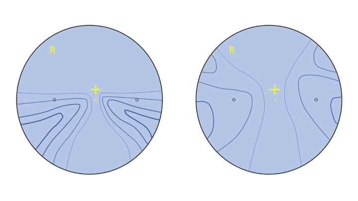 Figure 1: Schematic representation of hard (left) and soft (right) progressive lens designs
Different manufacturers use different methods to represent their designs, the most commonly used being iso-cylinders, represented by the blue lines on each diagram, of increasing thickness, each step representing 0.50DC of unwanted astigmatic error. Much like contour lines on a map represent points of equal height, iso-cylinders represent points of equal aberrational astigmatism.
It can be seen that the hard design has a greater level of aberration over a smaller area, and although this allows good-sized distance and reading areas means the intermediate is too narrow for many users and the lens is comparatively difficult to get used to since the aberration creates distorted images in the periphery, which can cause a head-swimming swaying or rocking effect, particularly when moving around, and especially if the lenses have been dispensed with sub-optimal fitting parameters.
Soft design varifocals have a wider intermediate area, and the level of aberrational astigmatism is less because it is spread out over a wider area, encroaching upon both the distance and near vision compared to the hard lens equivalent in the same prescription. Because the unwanted aberration is at a lower level than with harder designs, it is less noticeable and easier to tolerate, and as a result, soft designs are easier to adapt to than hard ones.
In reality, the classic lenses that bore the descriptions hard (such as Sola Graduate, AO Truvision), and soft (such as Sola XL, AO Pro) are either little used or long-since discontinued. The world has moved on to extra-soft and ultrasoft designs that push the iso-cylinders and distortion to the periphery of the lens at levels that are less noticeable to the wearer. For a while, some lenses were described as ‘firm’ designs, which meant a distortion-free distance portion with softer design characteristics for intermediate and near than a hard design. This term now seems to have fallen into disuse, although many personalised lenses could be described in this way.
Another important concept is horizontal symmetry, which means that, regardless of prescription, the right and left lenses are balanced. So, when looking left, for example, through the distorted part of each lens, the aberration experienced by each eye through the temporal area of the left lens and the nasal area of the right lens is the same. This is a lot easier to tolerate and adapt to than when each eye sees different distorted images.
In addition to iso-cylinder contour plots, there have been several other methods of representing progressive lens designs including vector plots (showing individual points of astigmatism and incorporating the axis direction) and iso-power/mean addition diagrams (which better quantify the usable areas of the lens rather than the areas of distortion). The most popular in practice is the simple sketch showing the wider zones for distance, intermediate and near that should accompany the patient’s upgrade journey from ‘basic’, through ‘good’, and ‘better’ to ‘best’ lens options. It is important to recognise that such sketches and the plots in figure 1 do not represent the experienced reality of lenses since there are so many variables to consider.
For example, traditional PPLs always have the progression on the front surface, whereas many freeform lenses have the add on the back, and others have it split between the two surfaces either spherically or utilising camber technology (figure 2), which utilises a continuously variable cylindrical component on the front surface, not unlike an elephant’s trunk, with a vertical axis and power increasing (radius of curvature decreasing) towards the bottom. Camber technology produces semifinished lenses with an increasing cylindrical component (axis vertical) on the front surface. The back surface is worked with perpendicular cylinders to create spherical add power, compensated of course for any cylindrical component required in the main lens prescription.
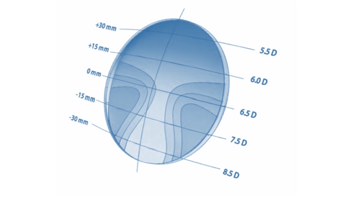 Figure 2: Camber technology
Due to the complexity of lens surfaces and the variability of astigmatism levels even within the same lens design, iso-cylinder plots and similar illustrations can only offer the most basic of guides to the quality of a lens. It should be born in mind that the shorter the corridor length and the higher the reading addition, the harder a lens design and the more noticeable peripheral lens aberrations become. Additionally, the availability of as-worn lens adaptations, where the lens powers are compensated for base curve, wrap angle, pantoscopic tilt and so on, make comparisons essentially meaningless unless specific to the actual lens in question.
Nevertheless, when a patient presents with progressive lenses from elsewhere it is very helpful to know what kind of lens they are wearing, and if this cannot be identified from the engravings, it is important to still be able to gauge the quality of lens and design philosophy. A simple technique is to view graph paper through a lens, holding the spectacles 15 to 20cm from the grid and viewing from a normal near working distance of around 40cm (figure 3).
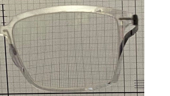 Figure 3: Graph paper can provide a simple analysis of lens aberrations
The best method of comparison is to invest in a computerised lens analyser specifically designed for the job, such as the Eyoto eMap (figure 4). Such devices are available in laboratory and practice (retail) editions and include the ability to verify finished spectacles, measure and categorise existing progressive lenses and may even identify what brand of lens the patient is wearing. Retail editions also include interfaces to tablet computers to assist in the dispensing process in terms of demonstrating lens options to patients thereby allowing them to make properly informed decisions.
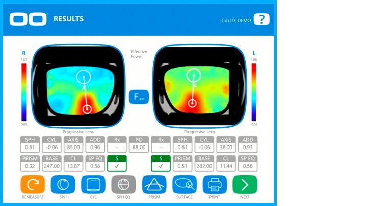 Figure 4: eMap makes PPL analysis easy. Photo courtesy eyoto.com
Lens markings
Permanent markings
All varifocal lenses have laser engraved verification markings so that the lenses can be identified, orientated correctly when glazing, and subsequently checked and verified. These permanent markings are indicated by the black markings on the lens shown in figure 5. The two orientation markings are always separated by a standard 34mm between centres, which corresponds with the distance between the outer ink markers on a focimeter. Markings take many forms, most commonly two small circles as shown in the figure, however they can be any shape: oval, diamond, triangular, a cross, etc. Many manufacturers prefer to use stylised initial letters relating to their company name: E for Essilor; H for Hoya; S for Shamir, Seiko and Sola; Z for Zeiss, and so on. Others prefer to place their branding separately on the lens either above the temporal engraving or above or below the nasal marking.
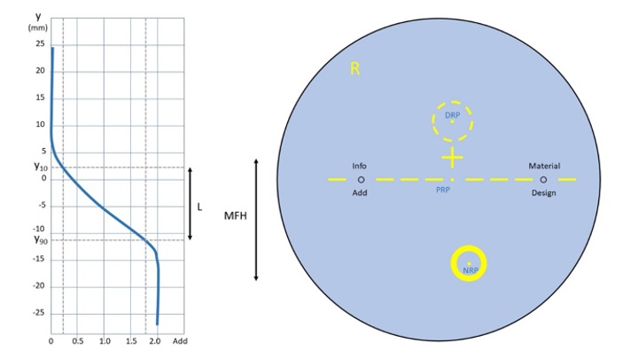 Figure 5: A 60/65 decentred progressive lens showing permanent (black) and temporary (yellow) markings and major reference points (labelled in blue). The graph shows power profile of the lens (plano with +2.00 add) relating corridor length, L, to minimum fitting height, MFH
It seems that the only consistently applied rule with regards to permanent markings is that the reading addition is always engraved below the temporal marking, often in shortened form, (eg 20 = +2.00, 22 = +2.25) and always without the + or the decimal point.
The other permanent markings (indicated by design, material, and info on the lens figure 5) are used by manufacturers to record other information that will help laboratory staff and practitioners to identify the lens and verify that what has been ordered has been supplied.
Design
Design refers to the varifocal type. Markings range from simple abbreviations, letters, numbers, and symbols to a picture of a training shoe for Shamir Run. It is a sad fact now that unless you specialise in one or two manufacturers’ lenses the chance of remembering any one manufacturer’s engravings is remote indeed given the wide range of designs available. It is essential therefore to have a good reference guide and although resources such as ABDO’s Ophthalmic Lens Availability remain useful they are inevitably out of date as soon as they are published and there is no substitute for manufacturers catalogues and websites.
Material
Material details concentrate principally on abbreviating the refractive index: 6 for n=1.6, 67 for n=1.67 and so on. Standard index (CR39, n=1.498) is not normally engraved. Some manufacturers also identify photochromic and tinted lens options within their engravings – for example, using Shamir again, TTX is Transitions Trivex, PZ6 is 1.6 polarised, PD is polycarbonate Drivewear and so on.
Info
Although there is no standardisation of how further information is presented in the hidden markings, the area marked info on the lens in figure 5 is likely to contain details of the base curve for individualised and sports lenses, and also corridor length or frame depth value, although some manufacturers, notably Zeiss list this information below the Add. Additionally, several manufacturers offer design variations within their individualised designs – for example Seiko lenses can be biased towards distance (engraved A), near (C) or balanced (B) and can also be specified with varying insets from 0 to 5mm which are also recorded on the lens.
Viewing permanent markings
Lens engravings are most easily viewed using a system specifically designed for the purpose such as the marking finders shown in figures 6a, 6b and 6c. The spectacles or uncut lens are held between the magnifier and the light source located below and the markings viewed. There is sufficient space to mark the engravings with a marker pen or China graph pencil.
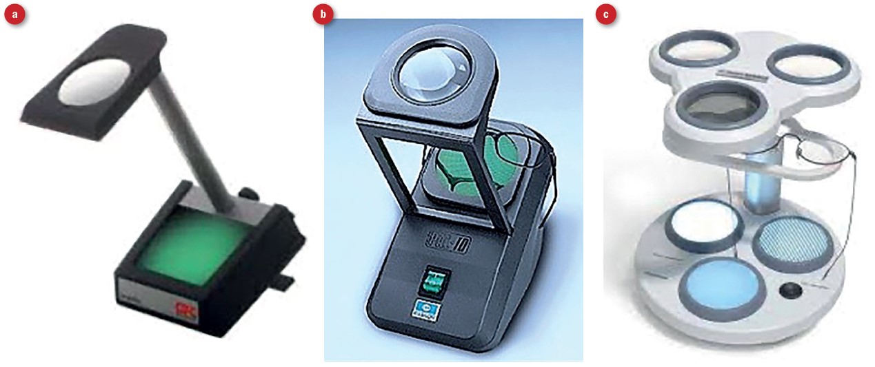 Figure 6: Left, marking finder available from Bondeye or Dibble Optical; centre, marking identifier from Essilor and right, marking finder with range of illumination and magnification
Markings are either produced when a semi-finished lens is moulded or are engraved on a finished lens after production using an excimer laser. The engravings are found on the side of the lens where the progression is located so may be on the front or the back surface. Each of these three types of marking require different kinds of illumination to be seen and the deluxe device shown in figure 6c is a worthy investment in busy practices and labs.
Viewing markings without such a device requires a flat light, such as fluorescent light, rather than the spotlights found in many practices, and may be made easier by having a black background and side illumination. Once the permanent markings have been located and marked the temporary marks can be added using a marker pen and lens template, or where that is not available a frame rule and knowledge of the position of major reference points, particularly the fitting cross, relative to the markings.
Temporary markings
All uncut progressive lenses are supplied with temporary wax or ink markings to aid with the glazing, verification and fitting process. They are most often yellow; however, some manufacturers use white, blue or green markings. The temporary marks include horizontal lines between and beyond the engraved circles, to aid in ensuring the lens is straight during marking and setting and when checking finished spectacles. It is also normal for the lens to be marked Right or Left, and also to have some branding identifying the manufacturer and/or lens design. Additionally, all lenses are marked with a fitting cross and the major reference points, as labelled in blue in figure 5:
- Distance reference point (DRP); marks the centre of the distance verification area. The dot shown in fig 5 is not universally printed on the lens, however the area surrounding it must be identified on the lens as this is where the distance prescription must be checked on the focimeter.
- Near reference point (NRP); marks the centre of the near prescription verification area. The dot shown in figure 5 is not printed on the lens, however the area surrounding it must be identified as this is where the near prescription must be checked on the focimeter.
- Prism reference point (PRP); is located midway between the circular micro-engravings, 17mm from each since they are 34mm apart. Any prescribed prism should be measured at this point as should any prism thinning. It is important to check for prism at the PRP on all orders to ensure there is no vertical imbalance. Note that there is almost always prism to be found at the PRP. Historically one would expect to find prism thinning equivalent to approximately two-thirds of the reading addition, and although free-form lenses, especially those with compensated powers can vary quite considerably. The example in figure 7, a Nikon PP12 lens, shows 0.62Δ base 270 (down) for an add of +1.08DS, which is broadly in agreement with tradition.
- Fitting cross; is located on the vertical line between the PRP and DRP and is the point on the lens that the manufacturer recommends should coincide with the pupil centre or visual axis when the eye is in the primary position. Most commonly the fitting cross is 4mm above the prism reference point (Essilor Varilux, Hoya, Optimum, Rodenstock, Tokai), however 0mm (Pentax, Rodenstock Impression ILT, and many occupational progressives), 2mm (BBGR, Nikon, Jai Kudo, Seiko, Younger, American Optical, Sola), 3mm (Pentax, some Norville) and 6mm (Zeiss, Rupp & Hubrach) are also used so it is best not to assume.
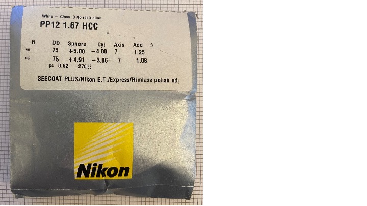 Figure 7: A personalised progressive showing ordered and compensated lens powers and prism thinning of 0.62Δ base 270
Removing temporary markings
Wax, ink and marker pen can all be removed with methylated spirit, acetone (not recommended), or a variety of proprietary cleaners sold for the purpose; however, inexperienced practitioners should be aware that this simple procedure can undo a host of good work by causing damage to the spectacles and leaving a lasting poor impression. Many frame materials (cellulose propionate, polyamide/Grilamid-type materials and some high gloss lacquers used on acetate and some metal frames) are damaged by the chemicals required to remove lens markings – the chance of this can be minimised by using specialist products such as Essiclean (figure 8), which are unlikely to damage frame materials.
 Figure 8: Specialist products remove lens markings effectively without damaging frames
Some products are packaged in a fibre-tip pen-like bottle that both applies the chemical and absorbs the ink. This also helps to avoid another common issue where meths is sprayed on the lenses and displaced marking ink ends up in the rim of the frame - the presence of yellow wax particles here is never desirable and a moment’s lapse in concentration can take many minutes to put right requiring complete disassembly and reassembly of the spectacles. If using meths it is best to dip a cotton bud or piece of soft tissue in the solvent so that the markings can be removed carefully without fear of damage to the frame or the spectacles’ appearance. Microfibre cloths should be reserved for the final polishing of a clean lens and not contaminated with ink or dirt, which should be removed by rinsing under the tap or with optical quality tissue and a cleaning spray.
Power profile, corridor length and minimum fitting height
Returning to figure 5, the graph shows the power profile of a progressive lens of plano distance prescription with a +2.00DS reading addition. The x-axis records the power of the lens along a line that passes through the DRP, PRP and NRP, which is plotted against y the displacement above or below the prism reference point (PRP). As might be expected the power at the distance reference point is plano, and at the near reference point the full addition of +2.00 is recorded. It can be seen that the progressive zone begins at a point about 7mm above the PRP and reaches full reading power at about 15mm below. This might lead to the conclusion that the corridor length is 22mm, however corridor length is defined in BS EN ISO 13666:2012 as the distance between y10 and y90, the points on the lens where 10% and 90% of the reading addition are realised respectively. In this fictitious lens, the corridor length, L, shown in figure 5 is approximately 14mm. The minimum fitting height MFH is a completely different value – from the fitting cross to the bottom of the near verification area that surrounds the NRP, here around 23mm. It is important to note that manufacturers can place the fitting cross below as well as above y10, and that the NRP can be much closer to the y90 depending on the lens profile. Currently, most freeform lenses and all individualised lenses come in a variety of corridor lengths with minimum fitting heights ranging from 14mm up to 26mm or more.
Dispensing PPLs
Frame selection
It follows from the above that a prime consideration, when dispensing PPLs, is to select a frame that has the appropriate depth to accommodate the minimum fitting height of the desired lens. Additionally, manufacturers recommend a minimum lens height above the fitting cross, typically 10-12mm but often much higher for occupational lenses, above the pupil centre to the top rim.
The frame as-worn should have a pantoscopic tilt of +9.5º +/-2.5º unless a personalised progressive lens is dispensed in which case a pantoscopic tilt between +30º and -10º may be possible depending on the lens design. Given the disproportionate effect even a small error in pantoscopic tilt can have it is also vital that angle of side (and thereby pantoscopic tilt) can be easily adjusted.
Where the lens is of conventional design and cannot be compensated for personalised parameters, the face form angle (also known as wrap, bow or dihedral angle) of the frame should be between 0º and 5º.
Although it is by no means necessary, it is advisable to select frames with adjustable pads on arms to give some flexibility to adjust fitting cross height, vertex distance, and even horizontal displacement of the fitting cross after the spectacles have been made. Having a range of plastic frames with adjustable bridges, as well as the usual metal and rimless styles is essential to avoid disappointing patients.
Measurements
How to take the various facial and ‘as-worn’ measurements has been covered in previous articles in this series, however they can be summarised as follows:
- Pantoscopic tilt and wrap angle; if outside the range for standard progressives advise another frame or select a personalised progressive lens to avoid inevitable patient complaints.
- Monocular PDs ideally using a pupillometer. Whatever method is used the fitting cross should be marked on the dummy lenses after measurement and then verified on the patient. Dotting pupil centre with a marker pen while the frame is in situ is the least reliable method since patients are likely to flinch either sideways, backwards or both.
- Monocular heights to pupil centre; unlike single vision lenses there is no need to compensate heights for pantoscopic tilt as this has already been taken into account by the manufacturer. With standard progressives the tilt should be 9-10º. If this cannot be achieved by adjustment, select a new frame or choose a lens that can be compensated for non-standard tilt values especially if below 7º or above 12º.
- Personalised measurements; in addition to pantoscopic tilt and wrap most manufacturers of personalised progressives also require vertex distance, working distance, corridor length, design bias (eg balanced, near and so on), and can also individually set the inset if required. Most manufacturers state that, if personal parameters are not provided, the calculation takes into account default parameters to optimise the lens. In reality, this is not personalising the lens and is, in this author’s opinion, why personalised lenses have not really caught on in the UK. They are only superior if the right measurements are measured correctly and properly taken into account.
Case study Dr J (GP)
Dr J, a 55-year-old general medical practitioner, purchased two pairs of varifocals, one to a black acetate RayBan Wayfarer style frame, and the second to a shallow Jimmy Choo frame with very thick diamante encrusted sides. The approximate Rx was +5.00/-2.00x180 R&L Add +2.00. On collection Dr J could see clearly for distance and read N5 with both pairs and went away wearing her RayBan spectacles. She returned six or seven weeks later on crutches and claiming that her varifocals were responsible for her falling down the stairs. She had worn her RayBans for three weeks without problem and took a trip to London to the theatre. She had arrived at her hotel, got changed, and as a finishing touch put on her blingy Jimmy Choo specs before running out of the door, when she promptly fell down the stairs. She sustained injuries that kept her off work for a fortnight and prevented her from exercising for over six months.
A standard approach (using a special triage form designed for the purpose) was then taken to assess whether what had been ordered had been supplied, and that the specifications were appropriate to the patient. The lenses were marked up and the fitting cross position located on each pair. The prescription was exactly as ordered and identical for both pairs with identical amounts of prism thinning. The lenses were the same in every way and both frames had been glazed correctly.
Dr J was booked in for a second sight test, which determined no change in prescription, and despite her complaining of increased peripheral distortion in the second pair was sent away to adapt to the spectacles. However, being a scientist Dr J could not logically accept that it was OK for her visual experience through two seemingly identical pairs of glasses to be so different. She returned again to complain and was offered a refund on the second pair of spectacles which she declined – she really liked the Jimmy Choo just wanted them to be fitted with lenses that she could see through as well as the RayBans. She wanted to get to the truth and to ensure patients were not put in harm’s way again, and therefore threatened legal action for compensation for her injuries. Head office got involved. Another sight test with a clinical governance optometrist and an appointment with a dispensing optician regional manager did not solve the problem either and so the author was invited to try.
The reason behind the difference in vision was simple. The centre of rotation condition was satisfied in the RayBans and was not in the Jimmy Choos. The RayBans had a pantoscopic tilt of 9º appropriate for the non-personalised PPLs whereas the Jimmy Choos were set at 3º and unfortunately due to the thickness of the side, and it not being possible to file it (due to diamante trim), the tilt could not be adjusted. Even if it had been possible, it turned out the practice did not have a device for measuring pantoscopic tilt and also lacked a decent selection of pliers (eg wide jaw angling pliers, parallel pliers) for adjusting it (as covered in previous articles in this series).
As Dr J loved the Jimmy Choo frame choosing a different one with an appropriate tilt was not an option, so the only option was to remake the spectacle with personalised individual lenses that took tilt into account. A couple of weeks later, when Dr J called to collect, the problem was solved. At least optically.
The author then had the small issue of legal action. Dr J agreed to drop the legal action if appropriate steps were taken to ensure such poor dispensing, and her injuries, did not happen again. All practices received pantoscopic tilt gauges and adjustment tools, a new visual concerns triage form was designed and launched with a specific guide to pantoscopic tilt included, and for those practices that needed it training was provided. In the practice that Dr J attended, a very large practice with very high sales, the training resulted in the rate of remakes and refunds reducing from over 20% to under 4% in just a few months. This increased profitability would have paid for the legal action had it continued, however the patient was happy with her result in the end even though it would not have been difficult to get it right first time and dropped her legal action.
PPL problem-solving
A best practice approach to dealing with patient concerns with progressive lenses is as follows:
- Check what has been ordered against the sight test and/or dispensing record for data entry errors.
- Locate hidden markings and mark up prism, distance and near reference points and the fitting cross position using a marking template.
- Check that the fitting cross is positioned as ordered both horizontally and vertically and also that the lenses are straight (ie not rotated clockwise or anticlockwise), and that the right and left lenses have not been switched (the Add is always temporally engraved to facilitate this), and that the lens has not been glazed upside down.
- Check the distance and near prescriptions are correct (using compensated powers if necessary – lens packets should be retained, or the compensated powers recorded on the computer at the time of initial verification) and that there is no vertical differential prism at the prism reference point (due for example to one lens being prism thinned and the other not, or having differing amounts, especially following a single lens reglaze).
- If using an automatic focimeter ensure it is in PPL mode and familiarity with the operating instructions. Consider double checking on a manual focimeter.
- Check the other hidden markings to ensure that the correct design, index, corridor length and add have been supplied.
If all is in order, only then do we check the spectacles on the patient:
- Check the fit of the frame, that it is well adjusted, level, and has not slipped down
- Check the pantoscopic tilt is 9-10º, or as otherwise specified if personalised lenses
- Check the wrap angle close to 0º, or as otherwise specified if personalised lenses
- Check the back vertex distance (BVD); regardless of prescription fitting the lenses as close as possible maximises field of view and therefore intermediate and reading width
- Ensuring you have adjusted your chair to ensure your eyes are level and that you are sat squarely in front of the patient, check that the fitting cross coincides with the pupil centre.
- Try to observe the patient while talking to see how they ‘relax’ and what happens to their head position and also check fitting cross position with the patient standing up
If there is error in any one of these factors they need to be corrected, and if this cannot be achieved through frame adjustment then it will be necessary to re-dispense the patient with either new measurements, new frames or personalised progressives depending on the circumstances.
Dr J’s case explained
It is easy to think when dispensing that all patients experience varifocals in the way that our schematic diagrams (figure 1), common on dispensing mats and iPad dispensing apps, show them to work. The reality is somewhat different and is dependent on many variables.
Consider figure 9a, which shows the as-worn iso-cylinder plot (in 0.50 steps) for a high quality but traditionally designed PPL +5.00DS Add +2.00 that is positioned at the optimum pantoscopic tilt of 9º. The patient experiences the promised wide distance portion, and good intermediate and near areas. In all the following lenses the BVD is optimised at 9mm. A close BVD is vital in all PPL dispenses.
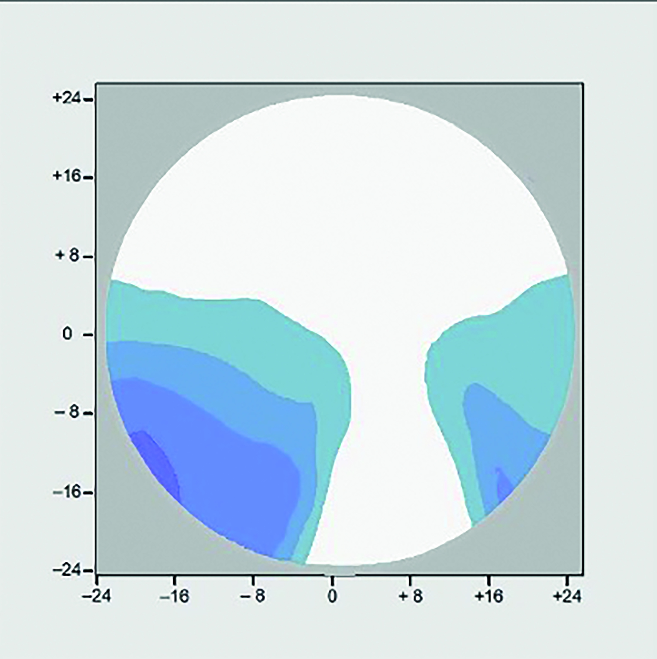 Figure 9a: +5.00DS Add +2.00 Panto 9o
Now consider the same lens dispensed in a frame with an as worn pantoscopic tilt of 3º (figure 9b). It can be seen that the amount of aberrational astigmatism has increased in both level, and area, and the patient experiences a narrowing of field of view in all three portions of the lens, despite the lens, as checked on the focimeter, being identical to the one in fig 9a.
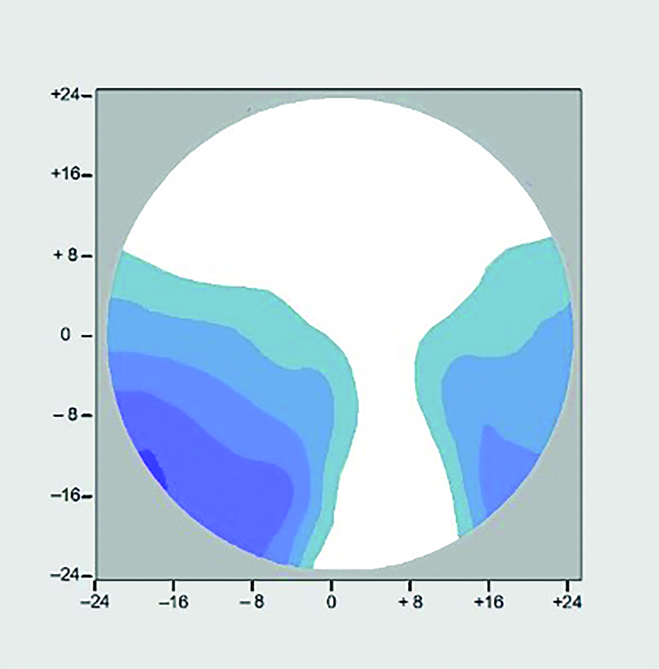 Figure 9b: +5.00DS Add +2.00 Panto 3o
It is a simple matter to prove that by tilting a spherical lens on the focimeter it becomes a sph/cyl, however what happens when a sph/cyl lens is tilted before the eye in a way that the centre of rotation condition is no longer satisfied is more difficult to visualise. Dr J’s prescription was approximately +3.00/+2.00 x 90 Add +2.00 and figure 9c shows the situation with her RayBan frame with optimum pantoscopic tilt of 9º. It should be noted that for an astigmat this situation is as good as it gets with conventionally designed PPLs and it is clear that compared to a spherical ametrope with a prescription of the same order of magnitude, in order to provide intermediate and near performance on a par with the spherical Rx, the width of the distance portion is severely compromised.
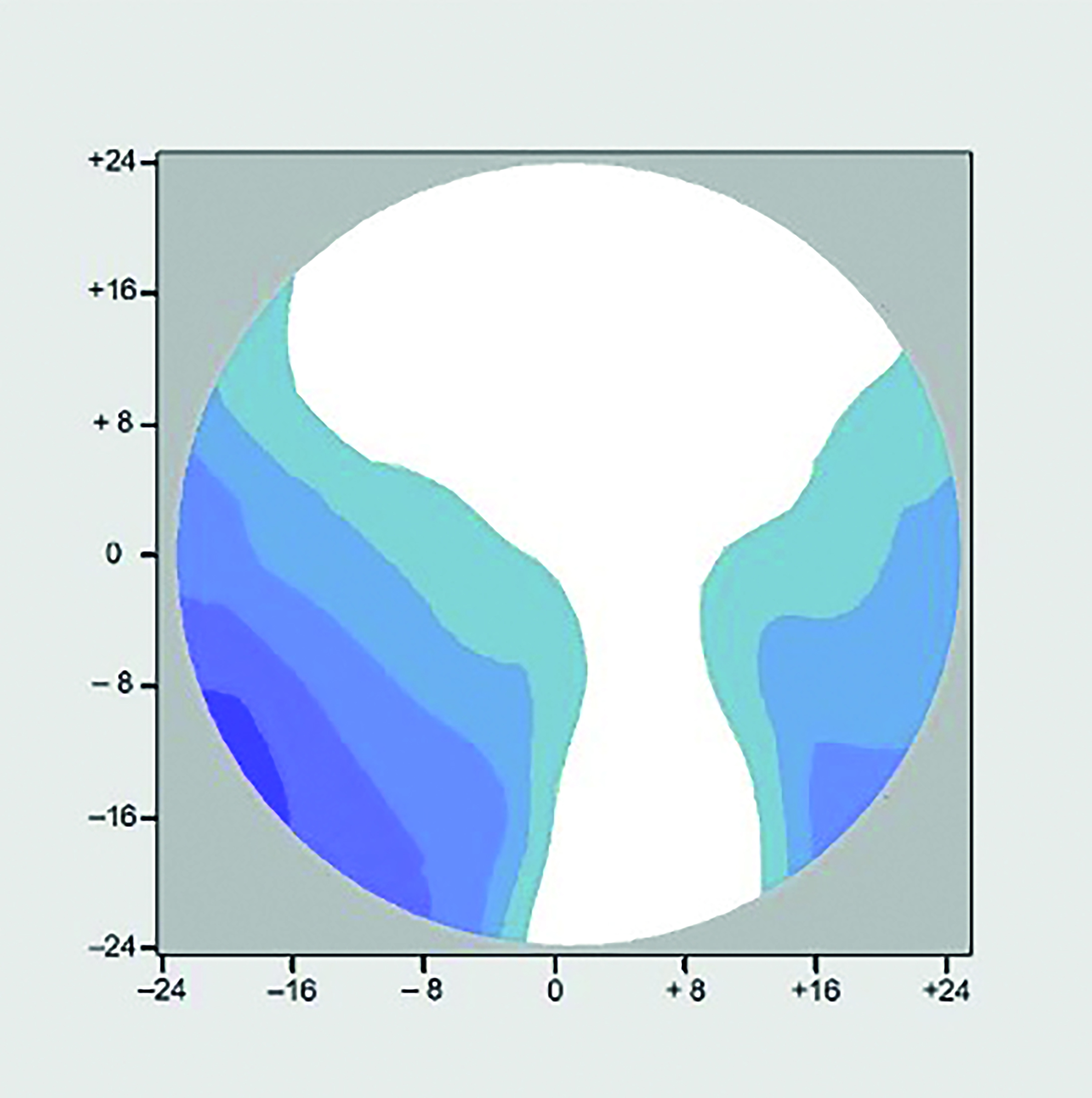 Figure 9c: R.E. +3.00 / +2.00 x 90 Add +2.00 Panto 9o
Remembering that in fig 9c the lens has been dispensed with all parameters at the optimum for its design, it is hardly surprising some patients feel their lenses do not live up to the expectations that were set for them by the images they were shown in practice during the dispensing process, however the reality can be much worse than that as Dr J can testify. Figure 9d shows the same lens in 9c but at a pantoscopic tilt of 3º. Note that the aberrational astigmatism has increased from 2.50D to 3.50D and now covers a much wider area, including the entire reading portion of the lens. It may be, depending on the prescription that an extra +1.00DC will aid reading to some extent if oriented horizontally or vertically, however almost all practitioners will have come across patients, including existing wearers, who simply cannot read in their new PPLs no matter where they hold the text, or how they position their head. In almost all cases pantoscopic angle is the problem, although placing standard lenses in a wrapped frame (such as sunglasses or sports eyewear) will produce a similar effect and specialist personalised sports PPLs are essential to avoid disappointment.
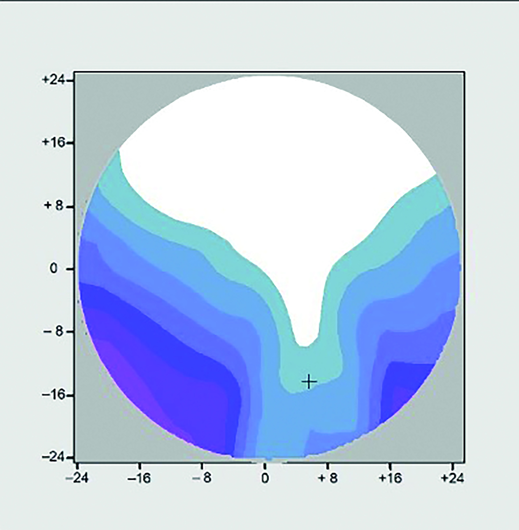 Figure 9d: R.E. +3.00 / +2.00 x 90 Add +2.00 Panto 3o
Dr J’s problems were eventually resolved using a personalised progressive lens with surface powers compensated for a pantoscopic tilt of 3º as shown in figure 9e. It is worth noting that taking into account individual face, frame and as-worn measurements improves the performance of the lens beyond even the most optimally fitted traditional lens design. The distance area is much larger than either of the previous two lenses (9c and 9d) and it can be seen that the reading and immediate areas have been restored to optimum levels because the aberrational astigmatism has been reduced in both level and area. While personalised lenses benefit all patients whose frame choice does not satisfy the centre of rotation condition they are also of benefit to patients who choose optimal frames if they have significant astigmatism, prescribed prism, or non-standard facial features such as narrow or wide PDs.
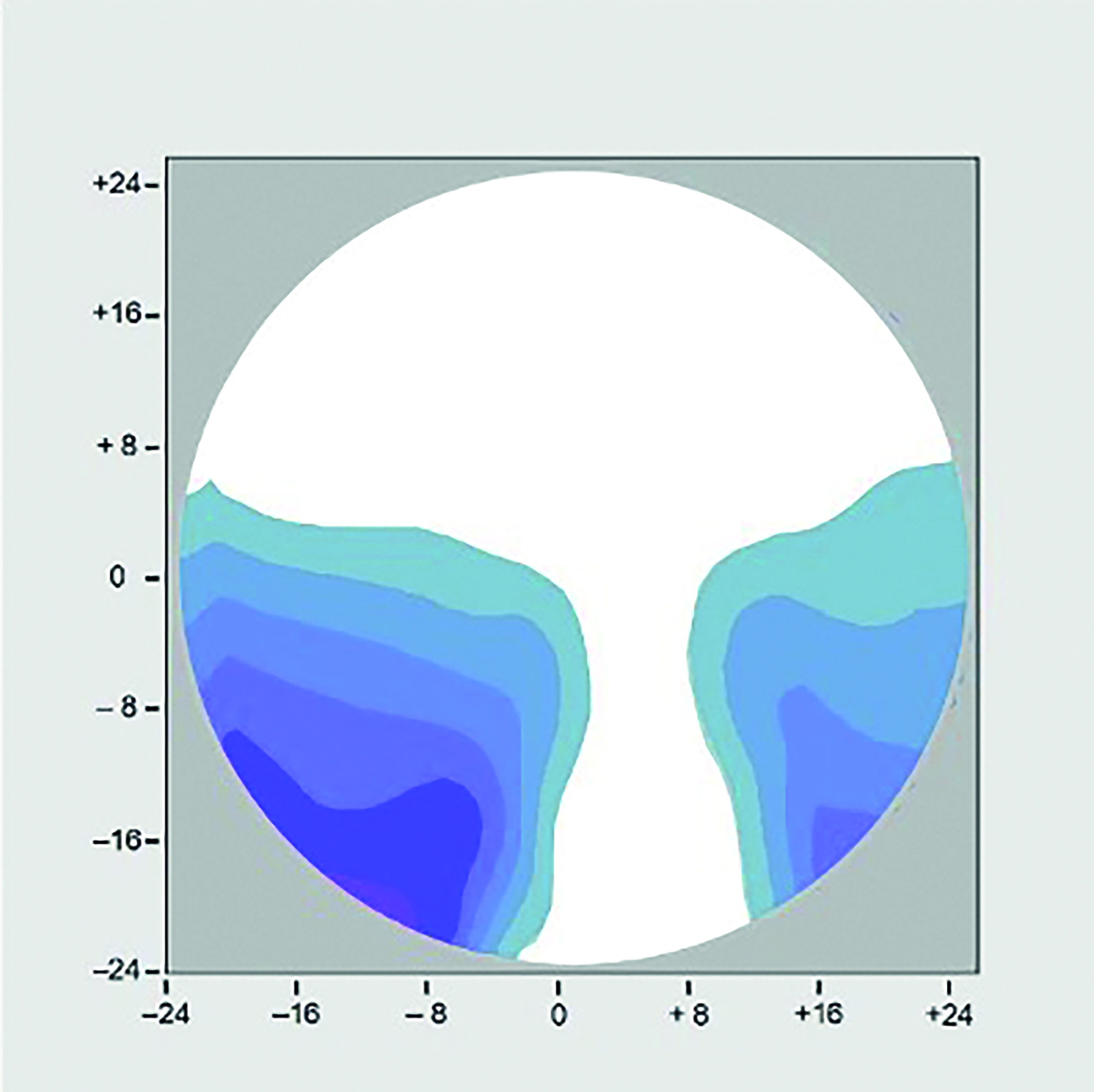 Figure 9e: R.E. +3.00 / +2.00 x 90 Add +2.00 Panto 3o; Personalised Progressive
Setting expectations
It is important to bear in mind that in most cases the patient is investing in new varifocals because their reading addition has increased, although there may of course have been a change in distance prescription too. In a given lens style, with an identical frame and measurement parameters, an increased add will always have the effect of ‘hardening’ the lens, increasing the distortion, and as a result narrowing the intermediate and reading areas. It is therefore important that the patient expects this and is also informed of higher quality lenses that may not suffer from this reduction in reading area. It is also important to note that even in identical lenses the reading and intermediate areas will always be reduced if the vertex distance is increased or the pantoscopic angle or wrap angle is set less optimally making frame selection vitally important in avoiding lens problems.
Eye versus head movement
It is best practice to ask the patient to leave the frame on while chatting to them so that the dispensing practitioner can observe the patient’s head movement in a more relaxed way and confirm that the heights are appropriate.
Observing how they use existing PPLs (or single vision distance glasses if a first time presbyope) in order to view a reading chart at different distances helps when considering to what extent they are an eye mover or a head mover when it comes to looking down. Essilor, when developing Varilux X-series, also introduced Near-Vision Behaviour Technology to measure this in practice, however with careful thought and observation, and a lens that offers a variety of corridor lengths and choice of balanced, near, and intermediate designs the same effect can be achieved manually.
Eye movers tend to prefer longer corridor lengths and deeper frames, whereas head movers with long progressive zones complain of feeling like ‘nodding dogs’, and are usually better off with shorter corridor lengths. Most patients when looking down however do a combination of tilting their head downwards and declining their eyes and are happy with a medium corridor length and a design suited to their most common visual task.
Patients can of course, especially for near vision, or when using tablet or laptop type computers also move the task/text so eye/head movement is more of an issue for intermediate tasks, which tend to be more fixed.
A common complaint is when patients move from shallow frames, with necessarily short corridor lenses, to deeper frames that may be more fashionable at the time. It may be tempting to increase the corridor length to match the new frame however this fundamentally changes the balance between head and eye movement that the patient has adapted to and is to be avoided unless the current balance is itself problematic. Intermediate issues are rarely solved with longer corridor PPLs and a second pair of occupational lenses should be offered instead.
Inset
Personalised progressives can also take into account lateral near vision behaviour as many patients have a tendency to hold their head to one side when reading and may require asymmetric insets. A special case of this is the monocular patient who will likely face their eye to their visual task, whether for distance or near, so that they have a broadly symmetrical field of view to the left and right. Such patients usually look straight down for reading without any convergence and would require an inset of 0.
Monocular patients who still have some vision in the other eye (due to severe amblyopia or pathology) can create problems of non-tolerance if dispensed single vision balance lenses – it is important to match the prism thinning of the PPL to avoid problems associated with differential prism if, despite one eye being blurred, the binocular fields still coincide.
Case study Dr S (Doctor of Law)
Dr S, a lawyer, and first time PPL wearer who had had separate pairs of distance and reading spectacles previously, but now required an intermediate prescription for the computer, was dispensed a top-quality traditional PPL but was unhappy with the performance and had repeatedly returned to the practice to complain. Several retests and pairs of lenses later he complained to head office and made a legal claim for loss of earnings for his legal practice at his normal charge out rate of £1,000 per hour.
The lawyers were prepared to settle for £12,000, however that would not be in his best interests as his problem would not have been solved so it was decided to have a last-ditch attempt at providing a pair of spectacles Dr S could use.
After several telephone conversations with both the patient and the practice it was clear that the patient was more used to talking than listening, however, he did have a justifiable complaint, since his original concern was using the computer. The decision was made to make the 200-mile journey to see the patient in person, and as he refused to set foot in the practice, to visit the patient at home.
Aside from the obvious wealth two things were striking about Dr S. Firstly he was very tall, and secondly, he sat very upright. On moving to his home office/library to take measurements of his workstation the reason for his posture became obvious as he had a large scar on his neck, which was revealed as due to spinal surgery and had left Dr S as a very definite eye mover with virtually no head movement unless it came from flexing his back rather than his neck. Interestingly he found the varifocals he had been supplied with fine for walking around in but not for other tasks. His computer monitor was very large, and set very high on a pile of encyclopaedias, and often had multiple pages of text open at once. Close work was also important – reading legal papers, law reports etc.
Using the convenient example of the cars on his drive it was a simple matter to explain that a Ferrari, a Range Rover and a Rolls Royce are all great cars, but they cannot all do the same thing, and so it is with spectacles. Additionally, it was explained that if a Range Rover is to be used habitually off-road it might be set up somewhat differently than when used as a Chelsea tractor.
Fundamentally pantoscopic tilt was a problem due to the patient’s unnatural head posture when the eyes are in the primary position, and this was complicated by the lack of head movement, which meant the right power had to be in the right place when required as it was not simply a matter of pointing the nose and altering the height of the chin as is so often advised on collection. The solution was to dispense four different pairs of spectacles – all personalised for pantoscopic tilt and other measurements: single vision distance for driving; individualised progressive lenses for general use; single-vision-intermediate for exclusive computer use; and a pair of individualised 2m room distance occupational lenses for mixed use – meeting with clients, computer and reading.
Once delivered and personally fitted, although at first confused by the need for so many pairs, Dr S was delighted to discover his principal problems had been solved. A few weeks later a courtesy phone call revealed ongoing satisfaction and that the threat of legal action had been withdrawn. The legal department considered four free pairs of spectacles money well spent.
Conclusions
It is disappointing to reflect that over 20 years since they were introduced personalised progressive lenses represent a tiny minority of varifocals dispensed in the UK. A failure to select frames with an appropriate pantoscopic tilt and wrap, so that the centre of rotation condition is satisfied, and a failure to select frames with the smallest possible vertex distance to maximise field of view, leads inevitably to disappointment for many patients. A failure to get it right first time costs the industry a fortune in remakes, refunds, and unnecessary retests. Justifiable complaints, usually because the as-worn pantoscopic angle is not optimum, are often palmed off as adaptation issues.
Which eye care practitioner has not heard repeatedly the resulting story of a patient who has given up complaining, with their glasses left sitting in a drawer somewhere, and the patient resorting to their old bifocals, the internet, or ready readers in order to see, until out of frustration they resolve to find a new optician. Investing in the right equipment, training, knowledge and skills to competently dispense varifocal lenses is probably the greatest factor in building patient loyalty available and could certainly enhance the reputation of the sector.
- Peter Black MBA FBDO FEAOO AFHEA is Course Lead for BSc (Hons) Ophthalmic Dispensing at the University of Central Lancashire, Preston, and is a practical examiner, practice assessor, exam script marker, board member and past president of the Association of British Dispensing Opticians. Tina Arbon Black BSc (Hons) FBDO CL is director of accredited CPD provider Orbita Black Limited, an ABDO practical examiner, practice assessor and exam script marker, and a distance learning tutor for ABDO College.
Useful reading
The following texts were used in the compilation of this article:
- Jalie, M. The Principles of Ophthalmic Lenses. 6e. 2021. ABDO
- Alonso, J et al. Modern Ophthalmic Optics. 2019. Cambridge
- Gilbert, P. Ophthalmic Lens Availability. 2015 and 2018 editions. ABDO
- BS EN ISO 13666:2012 British Standards
- Jalie, M. Ophthalmic Lenses and Dispensing. 3e. 2008. Butterworth-Heinemann
- Brooks, C., Borish, I. System for Ophthalmic Dispensing. 3e. 2007. Elsevier
- Tunnacliffe, A. Essentials of Dispensing. 1998. ABDO
- Griffiths, A. Practical Dispensing. 2000. ABDO